18
248 BAY SERIES
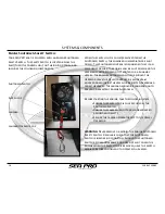
Engine Shutdown Safety Switch:
Your
SEA PRO
boat is Equipped with an Engine Shutdown
Safety Switch. The Safety Switch is located below the
Shift/Throttle Control Unit, on the Ignition Panel, and
includes the following components:
Shutdown Switch
Switch Clip
Lanyard
Lanyard Operator Clip
When the switch clip is pulled/removed from the
Shutdown Switch, the engine will immediately be shut
down. This Shutdown control is designed so that if an
emergency occurs, the engine will be shut down and the
vessel will not become out of control or a runaway
vessel. The Engine shutdown will occur should the
operator leave the Helm/Controls, be accidentally
knocked down inside the vessel or be ejected overboard
from the vessel. The lanyard should be long enough to
prevent inadvertent Engine Shutdown.
Before starting the engine, take the following steps:
•
Ensure the Switch Clip is fully secured in the
Shutdown Switch
•
Ensure the Lanyard is not tangled or wrapped
around any objects
•
Secure the Lanyard Operator Clip to the Vessel
Operator
WARNING
: Never remove or modify the Engine Shutdown
Safety Switch. Regularly check that the Shutdown
Switch is in working condition. Should the Shutdown
Switch become inoperable and does not shut down the
Engine when the Switch Clip is removed, have the switch
repaired before continuing to operate your vessel.
SYSTEMS & COMPONENTS
Summary of Contents for 248
Page 1: ...Owner s Manual and Quick Reference Guide 2017 WWW SEAPROMFG COM 248BAYSERIES ...
Page 39: ...248 BAY SERIES 39 SCHEMATICS WIRING DIAGRAMS 248 Bay Deck Wiring Harness Diagram ...
Page 40: ...40 248 BAY SERIES SCHEMATICS WIRING DIAGRAMS 248 Bay Hull Wiring Harness Diagram ...
Page 41: ...248 BAY SERIES 41 SCHEMATICS WIRING DIAGRAMS 248 Bay Battery Wiring Harness Diagram ...
Page 42: ...42 248 BAY SERIES SCHEMATICS WIRING DIAGRAMS 248 Bay Amp Power Wiring Diagram ...
Page 43: ...248 BAY SERIES 43 SCHEMATICS WIRING DIAGRAMS 248 Bay Dash Helm Switch Panel Diagram ...
Page 44: ...44 248 BAY SERIES SCHEMATICS WIRING DIAGRAMS 248 Bay Inside Helm Console Wiring Diagram ...
Page 46: ...46 248 BAY SERIES SCHEMATICS WIRING DIAGRAMS 248 Bay Hard Top Optional Switch Panel Diagram ...
Page 47: ...248 BAY SERIES 47 SCHEMATICS WIRING DIAGRAMS 248 Bay Hard Top Optional Wiring Harness Diagram ...

