24
248 BAY SERIES
3.
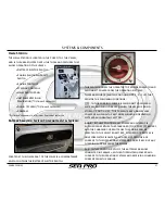
Open the flow control
valve (rotating counter
-
clockwise), located at the
top of the livewell, to
allow water to flow from
the pump into the livewell.
4.
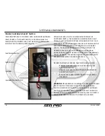
Turn the livewell pump on by flipping the switch on
the Helm Switch Panel that correlates to the livewell
you are intending to operate.
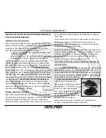
Once the water is pumping into the livewell, and has
filled the tank completely, adjust the flow control valve
to regulate the flow of water so there is a balance
between the incoming water flow and the exiting water
flow through the overflow valve. Rotating counter
-
clockwise will open the valve, allowing more flow, while
rotating clockwise will close the valve, reducing the
flow.
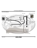
To drain your Livewells, flip the switch on the Helm
Switch panel to turn the pump off, close the seacock, and
position the drain valve to a Horizontal position in order
to open the valve.
Refer to the Pump Owner
’
s Manual for further
instructions, maintenance, and specification
information.
SYSTEMS & COMPONENTS
Summary of Contents for 248
Page 1: ...Owner s Manual and Quick Reference Guide 2017 WWW SEAPROMFG COM 248BAYSERIES ...
Page 39: ...248 BAY SERIES 39 SCHEMATICS WIRING DIAGRAMS 248 Bay Deck Wiring Harness Diagram ...
Page 40: ...40 248 BAY SERIES SCHEMATICS WIRING DIAGRAMS 248 Bay Hull Wiring Harness Diagram ...
Page 41: ...248 BAY SERIES 41 SCHEMATICS WIRING DIAGRAMS 248 Bay Battery Wiring Harness Diagram ...
Page 42: ...42 248 BAY SERIES SCHEMATICS WIRING DIAGRAMS 248 Bay Amp Power Wiring Diagram ...
Page 43: ...248 BAY SERIES 43 SCHEMATICS WIRING DIAGRAMS 248 Bay Dash Helm Switch Panel Diagram ...
Page 44: ...44 248 BAY SERIES SCHEMATICS WIRING DIAGRAMS 248 Bay Inside Helm Console Wiring Diagram ...
Page 46: ...46 248 BAY SERIES SCHEMATICS WIRING DIAGRAMS 248 Bay Hard Top Optional Switch Panel Diagram ...
Page 47: ...248 BAY SERIES 47 SCHEMATICS WIRING DIAGRAMS 248 Bay Hard Top Optional Wiring Harness Diagram ...

