


248 BAY SERIES
21
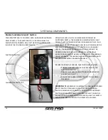
Helm Switch Panel:
The Helm Switch Panel contains all of the Activation
Switches and Circuit Breakers that control the Horn and
12
-
volt features installed on your vessel. This panel also
includes a 12
-
volt Power Accessory Port. The circuit
breaker for each switch/function is located directly
below that switch, and can be reset by pushing in the
button.
•
PUMPS
-
BILGE: Activates the bilge pump located in the
bilge
•
PUMPS
-
LIVEWELL 1 & LIVEWELL 2: Activates the pumps
that supply water to the livewells
•
PUMPS
-
FRESH WATER: Activates the pump that supplies
fresh water to the boat
’
s fresh water & shower system
•
PUMPS
-
RAW WATER: Activates the pump that supplies
raw water to the boat
’
s washdown system
•
LIGHTS
-
NAV: This is a three
-
position switch. Middle is
the Off position. Up activates the Navigation,
Instrumentation and Compass lighting. Down activates
only the Anchor Light
•
LIGHTS
-
CTSY/LIVE: This is a three
-
positon switch.
Middle is the Off position. Up activates all of the
vessel
’
s courtesy lights as well as the livewell lights.
Down activates only the livewell lights.
•
ACCESSORRY
-
1, 2, and 3: These activate any 12
-
Volt
Custom installed features or equipment
•
HORN: Activates the vessel
’
s horn and has an auto
-
reset position feature
The 12
-
Volt Power Accessory Port maintains power as
long as the Battery Selector Switch is in an
“
on
”
position.
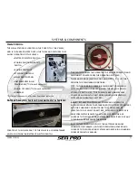
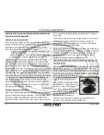
Compass:
Your
SEA PRO
boat comes standard with a Explorer
Surface Mount compass. Please refer to the compass
instructions for compensating and adjusting your
compass once all electrical equipment and unique
electronics are installed in your vessel, and once the
vessel is located in it
’
s operational area.
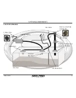
SYSTEMS & COMPONENTS
FPO
Summary of Contents for 248
Page 1: ...Owner s Manual and Quick Reference Guide 2017 WWW SEAPROMFG COM 248BAYSERIES ...
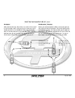
Page 39: ...248 BAY SERIES 39 SCHEMATICS WIRING DIAGRAMS 248 Bay Deck Wiring Harness Diagram ...
Page 40: ...40 248 BAY SERIES SCHEMATICS WIRING DIAGRAMS 248 Bay Hull Wiring Harness Diagram ...
Page 41: ...248 BAY SERIES 41 SCHEMATICS WIRING DIAGRAMS 248 Bay Battery Wiring Harness Diagram ...
Page 42: ...42 248 BAY SERIES SCHEMATICS WIRING DIAGRAMS 248 Bay Amp Power Wiring Diagram ...
Page 43: ...248 BAY SERIES 43 SCHEMATICS WIRING DIAGRAMS 248 Bay Dash Helm Switch Panel Diagram ...
Page 44: ...44 248 BAY SERIES SCHEMATICS WIRING DIAGRAMS 248 Bay Inside Helm Console Wiring Diagram ...
Page 46: ...46 248 BAY SERIES SCHEMATICS WIRING DIAGRAMS 248 Bay Hard Top Optional Switch Panel Diagram ...
Page 47: ...248 BAY SERIES 47 SCHEMATICS WIRING DIAGRAMS 248 Bay Hard Top Optional Wiring Harness Diagram ...