Scientek SW6000 Series Operating And Maintenance Manual Download Page 90

D-6

P

e

e

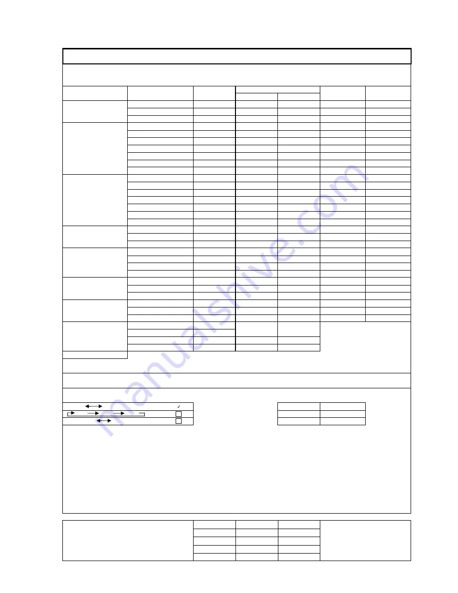
CYCLE 6: PROCESS NO DRYING

STEP

STEP

STEP

TEMPERATURE (°C)

WATER

DRAIN/HOLD

DESCRIPTION

STAGE

TIME (sec)

(1)

HEATING SP

GUARANTEE S

SUPPLY

PRESET

PREWASH

Fill

Cold

Washing

60

0

0

Drain

Drain

WASH-1

Fill

House Hot

Chem-1 Inject

15

Chem-1 Wash

180

60

0

Soaking

0

Neut-1 Inject

0

Neut-1 Circulation

0

Drain

Drain

WASH-2

Fill

House Hot

Chem-2 Inject

0

Chem-2 Wash

0

60

0

Soaking

0

Neut-2 Inject

0

Neut-2 Circulation

0

Drain

Drain

RINSE 1

Fill

House Hot

Washing

60

71

0

Drain

Drain

RINSE 2

Fill

House Hot

Rinse Aid Inject 

(2)

15

Washing

180

87

83

Drain

Drain

RINSE 3

Fill

House Hot

Washing

0

0

0

Drain

Drain

RINSE 4 

Fill

House Hot

Washing

0

0

0

Drain

Drain

EXHAUST

POV exhaust

0

-

-

Devaporizing

60

-

-

Drying - Steam

900 

(3)

85

57

Cool Down

20 

(4)

60

-

>   cycle end   <

Aqua-Pulse Settings:

SPRAY PATTERN:

SPRAY TIMES (sec):

         RH               LH      

Right Hand Puls

10

         RH              LH               Q/L  

Left Hand Pulser

10

         RH+Q/L               LH+Q/L 

Quick-Lock Puls

10

(1)

 To disable STAGE or STEP enter '0' for time setting

(2)

 Rinse Aid will be injected on the last rinse of the cycle

(3)

 Duration after the drying temperature has reached to TEMPERATURE GUARANTEE S.P. setting

(4)

 Duration after the drying temperature has fallen bellow HEATING S.P. setting

Scientek

Revision:

Date:

Name:

WASHER CONTROL SYSTEM

0

0

00-Jan-00

0

0

0

0

SW 6000 Series, Cart & Utensil Washer

Technology Corporation

0

0

0

PROGRAM CHARTS

0

0

A

Oct 01, 2007

D. Pekic

JOB #:    Standard

Summary of Contents for SW6000 Series

Page 1: ...her Model SW 6000 Revision 3 Sept 2007 SCIENTEK CART AND UTENSIL WASHER CAGE AND RACK WASHER Model SW6000 Series OPERATION AND MAINTENANCE MANUAL Scientek Technology Corporation Tel 604 940 8084 7943A Progress Way Delta BC V4G 1A3 Fax 604 940 8085 ...

Page 2: ...3 9 3 2 7 CYCLE INTERRUPTION 3 10 SECTION 4 DESCRIPTION OF CONTROL PANEL AND SWITCHES 4 1 4 1 POWER OFF ON 4 1 4 2 STOP 4 1 4 3 SERVICE OFF ON 4 2 4 4 REAR CLEAN END CONTROLS 4 3 4 5 STRIP PRINTER 4 3 4 6 PRELIMINARY PROCEDURE 4 4 4 7 LOADING THE WASHER 4 5 4 8 SHUTDOWN PROCEDURES 4 6 SECTION 5 PANEL VIEW TOUCH SCREEN CONTROL 5 1 5 1 MAIN MENU SCREEN 5 2 5 2 OPERATION SCREEN 5 2 5 2 1 CONTROL BUTT...

Page 3: ...T SIGNALS SENSORS 5 22 5 4 2 TEST PLC OUTPUT SIGNALS MOTORS VALVES LIGHTS 5 23 5 4 3 PRIMING CHEMICAL PUMPS 5 23 5 4 4 WASH SOLUTION RE CIRCULATION TANKS 5 24 5 4 5 TEST CONDUCTIVITY PH CONTROL SIGNALS 5 24 5 5 ALARM LIST 5 25 5 6 PASSWORD MANAGEMENT 5 26 SECTION 6 INSPECTION AND MAINTENANCE 6 1 6 1 CLEANING PROCEDURES 6 1 6 1 1 DAILY MAINTENANCE 6 1 6 1 2 WEEKLY MAINTENANCE 6 2 6 1 2 WEEKLY MAINT...

Page 4: ...T AND PLC WIRING CONNECTION DIAGRAM APPENDIX D PROGRAM CYCLE CHARTS 1 10 AND COMMON SETTINGS APPENDIX E SMC VALVE CONFIGURATION APPENDIX F PIPING AND INSTRUMENTATION DIAGRAM APPENDIX G PARTS LIST APPENDIX H FINAL RELEASE SHOP DRAWING APPENDIX I WARRANTY Scientek Technology Corporation Tel 604 940 8084 7943A Progress Way Delta BC V4G 1A3 Fax 604 940 8085 ...

Page 5: ...prevent falls keep floors dry Promptly clean up any spills or drippage WARNING BURN HAZARD Doors washer interior and washed wares may be hot Hot water steam may be sprayed through door opening if door is opened too soon press STOP button and wait until water flow stops before opening door Wear gloves and face protection WARNING PERSONAL INJURY AND OR EQUIPMENT DAMAGE HAZARD To avoid personal injur...

Page 6: ...otection WARNING ELECTRIC SHOCK AND OR BURN HAZARD Lock building electrical supply disconnect switch to OFF close steam water and air supply valves and position power switch to OFF before performing any service on the unit When the power switch in ON door switch s and valves are energized and if cycle is started hot water steam would enter piping and washer Wear gloves and face protection WARNING ...

Page 7: ... wash the load CAUTION EQUIPMENT DAMAGE HAZARD Use non abrasive cleaners when cleaning the unit Follow direction on containers and rub in back and forth motion in same direction as surface grain Abrasive cleaners will damage stainless steel Cleaner rubbed in a circular motion or applied with a wire brush or steel wool on door and chamber assemblies can be harmful to stainless steel Do not use thes...

Page 8: ...full control over the washer It facilitates easy access and adjustment of washer s operating parameters full access to ten pre programmed operating cycles and direct information feedback with Allen Bradley icrologix 1500 series Programmable Logic Controller P L C M WARNING PERSONAL INJURY AND OR EQUIPMENT DAMAGE HAZARD To avoid personal injury or equipment damage read and understand the manual Onl...

Page 9: ...ol panel is energized and if double door unit the rear clean end control panel is also energized Door switch s on the front soiled end and if double door unit rear clean end of the unit are energized The START STOP and other switches are also energized 3 If a door is open then the DOOR OPEN indicator or light red will illuminate If a double door unit then opening either door will illuminate indica...

Page 10: ...lso activated and the pump remains energized until the counter times out During the prewash the Aqua pulse control valves sequentially turn on and off the flow of circulating water to the left and right side spray arms and if so equipped the quicklock connection When the prewash counter has completed its time the drain delay counter is initiated During the drain delay all the Aqua pulse valves are...

Page 11: ...or message is displayed activates the pump signal that energizes the detergent pump When the detergent pump timer has reached its limit the detergent pump is deactivated WARNING CHEMICAL BURN EYE INJURY HAZARD When replacing chemical injection components or chemical containers residual detergent might remain in used parts or tubing Severe injury may occur in contact with skin or eyes Always refer ...

Page 12: ...lay the Aqua pulse valves are closed and the power drain timer is initiated During the power drain the drain line valve opens and the wash pump is energized This forces the bulk of the wash water from the sump to the sewer WARNING FALL HAZARD To prevent falls keep floors dry Promptly clean up any spills or drippage When the power drain timer has completed the gravity drain timer is initiated Durin...

Page 13: ...r The acid wash timer is also activated and the pump remains energized until the timer times out This step removes all of the scale and similar soils from the items being washed When the acid timer has completed the neutralizer pump timer is initialized This energizes the neutralizer pump and the NEUTRALIZER indicator is displayed and dispenses neutralizer into the unit The wash recirculation pump...

Page 14: ...n timer is initiated During the power drain the drain line valve opens and the wash pump is energized This forces the bulk of the wash water from the sump to the drain WARNING FALL HAZARD To prevent falls keep floors dry Promptly clean up any spills or drippage When the power drain timer has completed the gravity drain timer is initiated During the gravity drain the wash pump is deactivated and th...

Page 15: ...er has completed the drain delay timer is initiated During the drain delay all the Aqua pulse valves are left open and the water is allowed to flow out of the spray arms back to the sump At the end of the drain delay the Aqua pulse valves are closed When the drain delay timer has completed the power drain timer is initiated During the power drain the drain line valve opens and the wash pump is ene...

Page 16: ... times out This step provides thorough final rinsing of the items being washed and the inside of the cabinet During Rinse 2 the Aqua pulse control valves sequentially turn on and off the flow of circulating water to the left and right side spray arms and if so equipped the quicklock connection When the rinse 2 timer has completed its time the wash recirculation pump is deactivated and the controll...

Page 17: ...power operated damper to common house HVAC system or via dedicated exhaust blower In either case the P L C provides a dedicated signal to vent machine for timed period The message display will show exhaust time duration and will either command operation of damper or fan for given time When the exhaust timer signal is deactivated the exhaust display is extinguished The CYCLE END indicator message i...

Page 18: ...be hot Hot water steam may be sprayed through door opening if door is opened too soon press STOP button and wait until water flow stops before opening door Wear gloves and face protection The STOP button must be turned clockwise in order to release it The unit will not start so long as the STOP button is pressed and locked When the START button green is pressed the cycle resumes from where it left...

Page 19: ...P button and wait until water flow stops before opening door Wear gloves and face protection 4 2 STOP Red mushroom headed maintained two position switch must be out to Run This is used as an emergency stop button or temporary hold It is two stage button and must be turned clockwise in order to release it When pressed this button will stop the cycle and turn off the pump circulation tank sump heate...

Page 20: ...ing any service on unit WARNING PERSONAL INJURY AND OR EQUIPMENT DAMAGE HAZARD To avoid personal injury or equipment damage read and understand the manual Only qualified service personnel should make repairs and adjustments to this equipment Maintenance done by unqualified personnel or installation of unauthorized parts could cause personal injury or result in equipment damage Performance of sched...

Page 21: ...lumination Run light amber illumination Exhaust amber illumination Stop switch as described in 4 2 Start switch green momentary two position push button switch to re energize machine after Stop or to initiate start of cycle Exhaust switch black momentary two position push button switch to initiate additional exhaust venting time prior to unloading machine This is an additional exhaust time separat...

Page 22: ...door is opened too soon press STOP button and wait until water flow stops before opening door Wear gloves and face protection WARNING PERSONAL INJURY AND OR EQUIPMENT DAMAGE HAZARD To avoid personal injury or equipment damage read and understand the manual Only qualified service personnel should make repairs and adjustments to this equipment Maintenance done by unqualified personnel or installatio...

Page 23: ...lay or light is illuminated ensure that the doors are properly closed 4 If the STOP indicator is displayed or light is illuminated turn the STOP button in a clockwise direction to release it 5 Select the desired type of cycle using the touch pad cycle selection key see next section 6 Press the START button WARNING BURN HAZARD Doors washer interior and washed wares may be hot Hot water steam may be...

Page 24: ...supply valves for the unit 3 Position the building electrical supply switch circuit breaker to the OFF position Clean the unit as described in Section 10 Inspection and Maintenance WARNING FALL HAZARD To prevent falls keep floors dry Promptly clean up any spills or drippage Scientek Technology Corporation Tel 604 940 8084 7943A Progress Way Delta BC V4G 1A3 Fax 604 940 8085 ...

Page 25: ...aintenance Manual Scientek Washer Model SW 6000 Revision 3 Sept 2007 5 1 Section 5 Panel View Touch Screen Control Scientek Technology Corporation Tel 604 940 8084 7943A Progress Way Delta BC V4G 1A3 Fax 604 940 8085 ...

Page 26: ...w access to the setup and service menus Alarm list can also be accessed from the Main Menu Figure 1 MAIN MENU Screen Access to Operation Screen or Access to Set Up Menu Disabled Allowed or Access to Service Menu Disabled Allowed Note that the sign denotes that the key switch needs to be in the ON position in order to access the respective feature or Access to Alarm List no active alarms some alarm...

Page 27: ...t side of the screen there are three navigation buttons to the Main Menu Cycle Selection screen and the Alarm List screen Depending on the status of the washer operation the control and navigation button may change the color and the title as described below The top and central area of the screen provide the status information of the washer Control Cycle Stage Navigation Operation Step Figure 2 OPE...

Page 28: ...nge By pressing it again and holding it pressed for approx 3 sec it will reset the whole cycle Exhaust PB This button can be used at the end of a wash cycle to initiate extra exhaust or during a wash cycle after the Stop button stopped the cycle Quick Lock Valve On Off PB Depending on how a cycle was setup this button appears on the screen as either Q Lock ON or Q Lock OFF The button allows the se...

Page 29: ...tion is not possible at that stage In IDLE state operator is allowed to change the cycle selection The cycle list can be accessed and reviewed but the cycle selection can not be changed at that stage Main Menu Screen PB This button will bring up the Main Menu Screen Alarm List PB This button brings up the alarm list Gray button indicates that there are no active and un acknowledged alarms the blin...

Page 30: ... the cycle execution progresses the completed steps indication will become steady green with black letters The marks that the respective step has the temperature guarantee set If the temperature guarantee set point has not been attained within the specified time the step indication will become flashing red Stage Indicator The Stage Indicator provides information regarding the step currently being ...

Page 31: ...ration conditions of the control devices and the actions required by the operator Washer is ready for operation the operator is prompted to select a cycle and press the start button to initiate washing Washer is in operation The emergency stop button is pressed The temperature guarantee had not been achieved Operator should press the start button to re process the load Scientek Technology Corporat...

Page 32: ... or to drain the detergent solution after being used in the selected cycle The selection will default to RECYLE after the draining is finished The number on the button indicates how many times the detergent tank solution has been used since last draining Acid tank RECYCLE DRAIN button is used to select to weather to recycle or to drain the acid solution after being used in the selected cycle The s...

Page 33: ...he LOW pH alarm signal is present the system will engage the Acd Neut pump If the pH level can not be corrected in specified time period see section 7 11 an alarm will be generated and this screen will be shown The operator has option to repeat the neutralization stage or to proceed with the drain stage A message DRAIN pH LOW MANUAL OVERRIDE will be printed Pressing the button will toggle the sele...

Page 34: ... no access to other washer settings Password codes are required to access any selection from above The list with password codes is supplied separately from this document Access to the WASHER SET UP is allowed with valid password to the following users Supervisor Foreman and Service Access to the CHEMICAL SET UP SYTEM is primarily created for the chemical contractor to adjust the chemical injection...

Page 35: ...o any cycle Access to the control system configuration settings date time communication parameters etc is provided on this screen as a hidden button Press momentarily at the top right hand corner of the screen a numeric keypad will pop up Enter the password and the system configuration screen will be shown See the Panel View manufacturer s manual chapter 3 for explanation of the system menu The sy...

Page 36: ...n where you can enter a new value for the item After you have changed all desired parameters for a particular cycle press ACCEPT button accepting the changes or CANCEL button canceling the changes Use the AQUA PULSE FLOOR TILT button to access adjustment screen for aqua pulse spray pattern and the floor tilt if installed See section 7 1 9 for details Select next cycle you want to modify or press E...

Page 37: ... or the Guarantee temperature This will bring a numeric keypad to the screen where you can enter a new value for the item Note The guarantee set point can not exceed the sump heating set point After you have changed all desired parameters for a particular cycle press ACCEPT button accepting the changes or CANCEL button canceling the changes Select next cycle you want to modify or press EXIT button...

Page 38: ...e selections for the water supply are cold water usually used for the prewash usually 120 140 F around 180 F supply available supply available from the acid tank Wash 2 stage only ank and Acid Tank selection available only if optional reci installed U solution in the washer s sump on all stages except the Wash 1 and Wash 2 Pressing th button will toggle between DRAIN and HOLD selections In selecti...

Page 39: ...ycle can be locked out so that the cycle cannot be selected for operation Use UP or DOWN button to highlight the cycle you want to disable lock out or enable Pressing the SELECT button will toggle between ENABLED DISABLED Scientek Technology Corporation Tel 604 940 8084 7943A Progress Way Delta BC V4G 1A3 Fax 604 940 8085 ...

Page 40: ...UP or DOWN button to highlight the cycle whose label will be changed Press HANGE LABEL button to bring up an alphanumeric and enter desired description e Appendix B of this manual or PV600 manual page 5 11 for instructions of how to use the ypad ess EXIT button to go back to the Set up menu screen Ea ty makes sense to the operation personnel The label can be long 20 characters maximum U C Se ke Pr...

Page 41: ...screen allows to set the duration for of the cycle but will be continuously pressed or the Emergency cable pulled The siren will be timed on any alarm and ontinuous when the Emergency cable is pulled The siren could be enabled disabled by touching the SIREN button applies only if beacon siren are installed The wash solution re circulation tanks operation parameters are adjusted on this screen fill...

Page 42: ...l probes se DOWN button to highlight the item where you want to change the offset value and ess the ADJUST OFF SET button This will bring up a numeric keypad where you can ter a new value he Press EXIT button to go back to the Set up menu T U pr en The Actual temperature is the reading value plus t offset value screen Scientek Technology Corporation Tel 604 940 8084 7943A Progress Way Delta BC V4G...

Page 43: ...em provides up to eight characters for each label Use UP or DOWN button to highlight a label whose description you want to change ress CHANGE LABEL button to bring up an ASCII keyboard where you can enter a new P label description Press EXIT button to go back to the Set up menu screen Scientek Technology Corporation Tel 604 940 8084 7943A Progress Way Delta BC V4G 1A3 Fax 604 940 8085 ...

Page 44: ... selected the spraying pattern you may want to setup times for individual valves se UP or DOWN button to highlight the valve whose time on you want to change Press HANGE VALUE button to bring up a numeric keyboard where you can enter a new ticular cycle press ACCEPT button accept the changes or CANCEL button to cancel the changes ress EXIT button to go back to the Set up menu screen U C value Afte...

Page 45: ...or the PV600 User Manual page 3 28 for instructions on how to change the system date and time Note This procedure must be carried out by a quali accessing the control system set up parameters may O up enter the password The system ode screen will be shown Configuration fied person since any mistakes while render the control system inoperable Scientek Technology Corporation Tel 604 940 8084 7943A P...

Page 46: ...laneous Settings Access to this screen is provided by a hidden button on the Set up Menu Screen above the UP word The parameters in this section are factory set and normally do not require site adjustment Scientek Technology Corporation Tel 604 940 8084 7943A Progress Way Delta BC V4G 1A3 Fax 604 940 8085 ...

Page 47: ...ion in order to access the Service Menu screen 5 4 1 Test PLC Input Signals Sensors Both descriptive and graphical indication are used to better represent the status of the control device or the sensor Sample washer i e the sensors push buttons control valves pumps motors and chemical pumps The devices are divided in the following groups the PLC input signals the PLC output ignals the c s chemical...

Page 48: ...ate a device the correspondig button needs to be pressed To deactivate the device press the button again Any stop button will also deactivate all active devices The following safety features are built into the service mode None of the devices will activate if the cycle has been started or running Any stop push button will deactivate all active devices Wash Pump will shut down if the sump level swi...

Page 49: ...devices on the wash solution re circulation tanks can be tested from this screen transfer pumps and valves water supply valves and steam supply valve Note some devices may not be shown depending on the tank configuration used 5 Optional if pH or conductivity system is installed This the conductivity system and pH controller controller and m fe The pH controller sends the HI and L pH signals to be ...

Page 50: ...oll through Every alarm record has the date time stamp which system and tracking down the operational problems The red checkbox on the left side of each record indicates the acknowledgement status All alarms must be acknowledged in order to re start the washer s operation The ACKN ALL button will acknowledge all active alarms The CLEAR LIST button will delete all the records from the list The serv...

Page 51: ...ege erv sor or the factory access codes A 1 Turn service key ON 3 Touch Top Left corner of the screen 4 Enter the Supervisor or Factory access code the following screen will be displayed edly touchin 5 Select the operator whose access code needs to be changed by repeat button 6 Touch the NEW PASSWORD button and enter new password for the selected operator 7 Touch the VERIFY PASSWORD button to re e...

Page 52: ...supply switch to OFF before performing any service on unit Procedures described in this section should be performed at regular intervals as indicated The interval frequency should be increased with increased usage of the equipment Should a problem occur refer to Section 12 Troubleshooting 6 1 CLEANING PROCEDURES 6 1 1 Daily Maintenance 1 Debris Baskets and Screens After the last cycle of the day a...

Page 53: ...rifices o the hub assembly Position arm with orifices slightly off center No rocedure the header continues to rotate at less then 24 in the center of the hub by turning counterclockwise Remov into the hub to flush out all orifices Remov r surfaces of the hub Rem Reassemble Slide hub over axle and tighten hold down screw 2 R spray arms should rotate at about 24 r p m in a clockwise direction Becaus...

Page 54: ...itch to ON he OFF position Rinse Cycle or turn off the detergent pumps ART ompletion of the cycle press START again to run a second cycle in or ely rinse system pletion of second cycle open doo c C WARNING CHEMICAL BURN EYE INJURY HAZARD When replacing chemical injection components or chemical containers residual detergent might remain in used parts or tubing Severe injury may occur in contact wit...

Page 55: ...reign matter which can The self cleaning screen is located in the main drain line prior to the drain line valve clean it Secure with hardware previously removed making sure to tighten the nuts evenly Start the washer and check the cover for leaks a cycle with door s open or a do tio s nd start a cycle Wearing proper safety protection i e gloves slowly open door to check operation of automatic stop...

Page 56: ...pending on the amount of use the unit is receiving the Delrin rings in the spray arm hub ces assembly will need to be changed The Delrin kit comes in three 3 pie CAUTION The Delrin rings should be changed befor wear prematurely causing damage an e there is too much play in the les will d improper washing hub If they are not changed frequently enough the hubs and spind Remove the hold down screw in...

Page 57: ...unscrew the cap and remove re that the smooth side is facing up DO NOT use rough abrasives on the disk s surface The com assembl Shut o f Press n er bowl to release moisture and trapped air and equired T p the strainers on the sump and heat aine ha str th r s a hex cap which can be removed to extract the mesh scre cre ns and replace them in the strainers Open the building supply lines and check fo...

Page 58: ... meet the standards of material and performance set forth in this inal washer pipe size door for smooth operation Check that door handle and door catch are securely fastened to door 4 ol wiring and connections all rotary spray arms Check that they rotate freely 6 a Quicklock system check that the fit between the Quicklock Items which do not comply to test procedures must be corrected and retested ...

Page 59: ...g with er level in the sump Adjust the fill delay timer 8 efore st the the blower and erature device and compare it with the reading on the temperature display If it is out of adjustment refer to Temperature Offset Adjustment Section 5 3 1 7 4 Press the START button Ensure that the machine door is closed and the DOOR OPEN indicator light is not illuminated 5 Operate 6 fresh water and check the wat...

Page 60: ...utility supply lines 3 Position 4 Replace 5 Inspe 6 Clean unit as describe in Section 10 1 2 1 1 Verify that the CY e STOP button and verify that the STOP indicator display and light is illuminated unit will not operate with the STOP button 4 7 5 CLEANUP 1 building electrical supply disconnect switch circuit breaker in the OFF position any access panels that were removed work area to be sure all m...

Page 61: ...use personal injury or result in equipment damage preventive maintenance and minor r WARNING ELECTRIC SHOCK AND OR BURN HAZARD Lock building electrical supply disconnect switch to OFF close steam water and air supply valves and position power switch to OFF before performing any service on the unit When the power switch in ON door switch s and valves are energized and if cycle is started hot water ...

Page 62: ...mn that most nearly corresponds with the position to which the washer cycle progressed before the trouble occurred TROUB symp e CAU CORR to isolate and c the orde n which correct the problem with the use of the Tro oc th t is not described on the chart please call you local Scientek ver permit unqualified persons to work on the washer LE Select the problem you think is most appropriate to the part...

Page 63: ...ient or no water entering There is not enough water in the sump verify the float level and adjust as required chamber through rotary spray arms Rotary spray arm nozzles clogged clean nozzles Bottom filters clogged clean filters Self cleaning screen is clogged clean screen Drain valve is leaking replace if necessary Pump rotating in wrong direction check that pump is rotating correctly as indicated...

Page 64: ...Water goin heck the voltage to the solenoid Foreign ma jammed in solenoid Chamber g to overflow drain connections to switch Check operation of switch Clean switch contacts or replace switch as necessary ts er level is reached trical tch Clean ted prematurely Chamber float switch is malfunctioning check elec Pump star before appropriate chamber wat connections to switch Check operation of swi switc...

Page 65: ... the lines with hot water to remove any chemical buil or replace the lines if necessary Output is not energized verify that the output t pumps is active and check wiring Check diagnostic PLC outputs with touch screen The machine hangs up in the middle of the cycle and temperature guarantee active d is uring noid supply pen t the wash step Temperature Set Point too high verify the Set Point and adj...

Page 66: ...ibrate temperature Temperature alarm setting is too high verify and adjust If steam heated unit faulty sump coil steam solenoid supply valve repair or replace as necessary If steam heated steam supply valve If steam heated unit s clean If electrically heated unit sump heating element bu replace If electrically heated unit sump heater starter o tripped reset overload relay If electrica replace if n...

Page 67: ...ve is not energized check output to drain valve and check wiring Drain line plugged clear drain line Check PLC output with diagnostics through touch screen Chamber is covered in a white powder not draining properly check drain line valve operation Drain valve is not energized check output to drain valve and check wiring Drain line plugged clear drain line Detergent concentration is out of calibrat...

Page 68: ...Maintenance Manual Scientek Washer Model SW 6000 Revision 3 Sept 2007 8 1 Ap endi ACE S SERIAL p x A F PLATE PLATE Scientek Technology Corporation Tel 604 940 8084 7943A Progress Way Delta BC V4G 1A3 Fax 604 940 8085 ...

Page 69: ...aintenance Manual Scientek Washer Model SW 6000 Revision 3 Sept 2007 8 1 Appendix B PROGRAM INPUT OUTPUT ADDRESSES Scientek Technology Corporation Tel 604 940 8084 7943A Progress Way Delta BC V4G 1A3 Fax 604 940 8085 ...

Page 70: ... 0 12 I 0 0 13 FLOAT SW SUMP LEVEL SWITCH I 0 0 13 I 0 0 14 I 0 0 14 I 0 0 15 PULL CABLE EMERGENCY CABLE BREAK SIGNAL I 0 0 15 I 3 0 TC C1 SUMP TEMPERATURE SENSOR TC C1 I 3 1 TC C2 DRYER TEMPERATURE SENSOR TC C2 I 3 2 TC C3 BOOSTER HX TEMPERATURE SENSOR TC C3 I 3 3 I 3 4 I 3 5 I 4 0 00 FLOAT SW CHEMICAL 1 LOW LEVEL I 4 0 00 I 4 0 01 FLOAT SW CHEMICAL 1 NEUTRAL LOW LEVEL I 4 0 01 I 4 0 02 FLOAT SW ...

Page 71: ...POV O 1 0 04 O 1 0 05 SOL AIR BREATHER DAMPER POV 2 O 1 0 05 O 1 0 06 SOL AIR SECONDARY QUICK LOCK VALVE O 1 0 06 O 1 0 07 PILOT LIGHT P LIGHT STOP CLEAN SIDE O 1 0 07 O 1 0 08 PILOT LIGHT P LIGHT DOOR OPEN CLEAN SIDE O 1 0 08 O 1 0 09 PILOT LIGHT P LIGHT RUN CLEAN SIDE O 1 0 09 O 1 0 10 PILOT LIGHT P LIGHT EXHAUST CLEAN SIDE O 1 0 10 O 1 0 11 PILOT LIGHT P LIGHT CYCLE END CLEAN SIDE O 1 0 11 O 1 ...

Page 72: ... Manual Scientek Washer Model SW 6000 Revision 3 Sept 2007 8 1 Appendix C PANELARRANGEMENT AND PLC WIRING CONNECTION DIAGRAM Scientek Technology Corporation Tel 604 940 8084 7943A Progress Way Delta BC V4G 1A3 Fax 604 940 8085 ...

Page 73: ......

Page 74: ......

Page 75: ......

Page 76: ......

Page 77: ......

Page 78: ......

Page 79: ......

Page 80: ......

Page 81: ......

Page 82: ......

Page 83: ......

Page 84: ...ce Manual Scientek Washer Model SW 6000 Revision 3 Sept 2007 8 1 Appendix D PROGRAM CYCLE CHAR AND COMMON SETTINGS TS 1 10 Scientek Technology Corporation Tel 604 940 8084 7943A Progress Way Delta BC V4G 1A3 Fax 604 940 8085 ...

Page 85: ...INSE 3 Fill House Hot Washing 0 0 0 Drain Drain RINSE 4 Fill House Hot Washing 0 0 0 Drain Drain EXHAUST POV exhaust 0 Devaporizing 60 Drying Steam 900 3 85 57 Cool Down 20 4 60 cycle end Aqua Pulse Settings SPRAY PATTERN SPRAY TIMES sec RH LH Right Hand Puls 10 RH LH Q L Left Hand Pulser 10 RH Q L LH Q L Quick Lock Puls 10 1 To disable STAGE or STEP enter 0 for time setting 2 Rinse Aid will be in...

Page 86: ...Washing 0 0 0 Drain Drain RINSE 4 Fill House Hot Washing 0 0 0 Drain Drain EXHAUST POV exhaust 0 Devaporizing 60 Drying Steam 900 3 85 57 Cool Down 20 4 60 cycle end Aqua Pulse Settings SPRAY PATTERN SPRAY TIMES sec RH LH Right Hand Puls 10 RH LH Q L Left Hand Pulser 10 RH Q L LH Q L Quick Lock Puls 10 1 To disable STAGE or STEP enter 0 for time setting 2 Rinse Aid will be injected on the last rin...

Page 87: ...Hot Washing 0 0 0 Drain Drain RINSE 4 Fill House Hot Washing 0 0 0 Drain Drain EXHAUST POV exhaust 0 Devaporizing 60 Drying Steam 900 3 85 57 Cool Down 20 4 60 cycle end Aqua Pulse Settings SPRAY PATTERN SPRAY TIMES sec RH LH Right Hand Puls 10 RH LH Q L Left Hand Pulser 10 RH Q L LH Q L Quick Lock Puls 10 1 To disable STAGE or STEP enter 0 for time setting 2 Rinse Aid will be injected on the last...

Page 88: ...ashing 0 0 0 Drain Drain RINSE 4 Fill House Hot Washing 0 0 0 Drain Drain EXHAUST POV exhaust 0 Devaporizing 60 Drying Steam 900 3 85 57 Cool Down 20 4 60 cycle end Aqua Pulse Settings SPRAY PATTERN SPRAY TIMES sec RH LH Right Hand Puls 10 RH LH Q L Left Hand Pulser 10 RH Q L LH Q L Quick Lock Puls 10 1 To disable STAGE or STEP enter 0 for time setting 2 Rinse Aid will be injected on the last rins...

Page 89: ... Washing 0 0 0 Drain Drain RINSE 4 Fill House Hot Washing 0 0 0 Drain Drain EXHAUST POV exhaust 0 Devaporizing 60 Drying Steam 900 3 85 57 Cool Down 20 4 60 cycle end Aqua Pulse Settings SPRAY PATTERN SPRAY TIMES sec RH LH Right Hand Puls 10 RH LH Q L Left Hand Pulser 10 RH Q L LH Q L Quick Lock Puls 10 1 To disable STAGE or STEP enter 0 for time setting 2 Rinse Aid will be injected on the last ri...

Page 90: ...ot Washing 0 0 0 Drain Drain RINSE 4 Fill House Hot Washing 0 0 0 Drain Drain EXHAUST POV exhaust 0 Devaporizing 60 Drying Steam 900 3 85 57 Cool Down 20 4 60 cycle end Aqua Pulse Settings SPRAY PATTERN SPRAY TIMES sec RH LH Right Hand Puls 10 RH LH Q L Left Hand Pulser 10 RH Q L LH Q L Quick Lock Puls 10 1 To disable STAGE or STEP enter 0 for time setting 2 Rinse Aid will be injected on the last ...

Page 91: ...Washing 0 0 0 Drain Drain RINSE 4 Fill House Hot Washing 0 0 0 Drain Drain EXHAUST POV exhaust 0 Devaporizing 60 Drying Steam 900 3 85 57 Cool Down 20 4 60 cycle end Aqua Pulse Settings SPRAY PATTERN SPRAY TIMES sec RH LH Right Hand Puls 10 RH LH Q L Left Hand Pulser 10 RH Q L LH Q L Quick Lock Puls 10 1 To disable STAGE or STEP enter 0 for time setting 2 Rinse Aid will be injected on the last rin...

Page 92: ...ot Washing 0 0 0 Drain Drain RINSE 4 Fill House Hot Washing 0 0 0 Drain Drain EXHAUST POV exhaust 0 Devaporizing 60 Drying Steam 900 3 85 57 Cool Down 20 4 60 cycle end Aqua Pulse Settings SPRAY PATTERN SPRAY TIMES sec RH LH Right Hand Puls 10 RH LH Q L Left Hand Pulser 10 RH Q L LH Q L Quick Lock Puls 10 1 To disable STAGE or STEP enter 0 for time setting 2 Rinse Aid will be injected on the last ...

Page 93: ...shing 0 0 0 Drain Drain RINSE 4 Fill House Hot Washing 0 0 0 Drain Drain EXHAUST POV exhaust 0 Devaporizing 60 Drying Steam 900 3 60 57 Cool Down 20 4 60 cycle end Aqua Pulse Settings SPRAY PATTERN SPRAY TIMES sec RH LH Right Hand Puls 10 RH LH Q L Left Hand Pulser 10 RH Q L LH Q L Quick Lock Puls 10 1 To disable STAGE or STEP enter 0 for time setting 2 Rinse Aid will be injected on the last rinse...

Page 94: ... Washing 0 0 0 Drain Drain RINSE 4 Fill House Hot Washing 0 0 0 Drain Drain EXHAUST POV exhaust 0 Devaporizing 60 Drying Steam 60 3 85 57 Cool Down 20 4 60 cycle end Aqua Pulse Settings SPRAY PATTERN SPRAY TIMES sec RH LH Right Hand Puls 10 RH LH Q L Left Hand Pulser 10 RH Q L LH Q L Quick Lock Puls 10 1 To disable STAGE or STEP enter 0 for time setting 2 Rinse Aid will be injected on the last rin...

Page 95: ...tra Exhaust 120 Emergency Exhaust 120 TEMPERATURE GUARANTEE HOLD TIME sec PREWASH 600 WASH 1 600 WASH 2 600 RINSE 1 600 RINSE 2 600 RINSE 3 600 RINSE 4 600 Scientek Revision Date Name WASHER CONTROL SYSTEM 0 0 00 Jan 00 0 0 0 0 SW 6000 Series Cart Utensil Washer Technology Corporation 0 0 0 PROGRAM CHARTS 0 0 A Oct 01 2007 D Pekic JOB Standard ...

Page 96: ... exhaust Devaporizing Drying Steam 3 Cool Down 4 cycle end Aqua Pulse Settings SPRAY PATTERN SPRAY TIMES sec RH LH Right Hand Puls 10 RH LH Q L Left Hand Pulser 10 RH Q L LH Q L Quick Lock Puls 10 1 To disable STAGE or STEP enter 0 for time setting 2 Rinse Aid will be injected on the last rinse of the cycle 3 Duration after the drying temperature has reached to TEMPERATURE GUARANTEE S P setting 4 ...

Page 97: ... EXHAUST Extra Exhaust Emergency Exhaust TEMPERATURE GUARANTEE HOLD TIME sec PREWASH WASH 1 WASH 2 RINSE 1 RINSE 2 RINSE 3 RINSE 4 Scientek Revision Date Name WASHER CONTROL SYSTEM 0 0 00 Jan 00 0 0 0 0 SW 6000 Series Cart Utensil Washer Technology Corporation 0 0 0 PROGRAM CHARTS 0 0 A Oct 01 2007 D Pekic JOB Standard ...

Page 98: ...nd Maintenance Manual Scientek Washer Model SW 6000 Revision 3 Sept 2007 8 1 Appendix E SMC VALVE CONFIGURATION Scientek Technology Corporation Tel 604 940 8084 7943A Progress Way Delta BC V4G 1A3 Fax 604 940 8085 ...

Page 99: ...ntenance Manual Scientek Washer Model SW 6000 Revision 3 Sept 2007 8 1 Appendix F PIPING AND INSTRUMENTATION DIAGRAM Scientek Technology Corporation Tel 604 940 8084 7943A Progress Way Delta BC V4G 1A3 Fax 604 940 8085 ...

Page 100: ...ting and Maintenance Manual Scientek Washer Model SW 6000 Revision 3 Sept 2007 8 1 Appendix G PARTS LIST Scientek Technology Corporation Tel 604 940 8084 7943A Progress Way Delta BC V4G 1A3 Fax 604 940 8085 ...

Page 101: ... Maintenance Manual Scientek Washer Model SW 6000 Revision 3 Sept 2007 8 1 Appendix H FINAL RELEASE SHOP DRAWING Scientek Technology Corporation Tel 604 940 8084 7943A Progress Way Delta BC V4G 1A3 Fax 604 940 8085 ...

Page 102: ...ating and Maintenance Manual Scientek Washer Model SW 6000 Revision 3 Sept 2007 8 1 Appendix I Warranty Scientek Technology Corporation Tel 604 940 8084 7943A Progress Way Delta BC V4G 1A3 Fax 604 940 8085 ...

Page 103: ...eration misuse or improper installation The obligations of the Company are limited to those set forth in this warranty which is given in lieu of all warranties conditions and liabilities whatsoever implied by statute common law or otherwise and the Company its servants and agents shall not be liable for any claims for personal injuries or consequential damages or loss however caused WARRANTY CLAIM...

Reviews: