background image

3.

Einzelnes / doppeltes Sprühen

Się

 können im Menü 

„Spr

ühmenge

” einstellen, ob die Maschine

 einzeln oder doppelt sprühen 

soll.


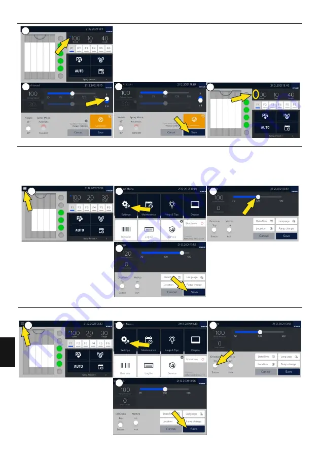
Drücken Sie dazu auf das Feld „Geschwindigkeit”

 (

Foto

 1)


<


Diese Funktion ist nur aktiv, 

wenn der Sprüh-Modus auf

 „

Standard”

 steht >


und wählen Sie dann die entsprechende Option 

(

Foto

 2)

 und bestätigen Sie die neue Einstellung durch Drücken von „Speichern”

 (Foto 3)

. Die 

Information zum einzeln oder doppelt Sprühen werden auf dem Display angezeigt 

(Foto 4)

.

3.5 

Pumpendruckeinstellung

Um den Druck der Pretreatment-Pumpe einzustellen, wählen Sie das Menü 

(

Foto

 1)


und den Punkt Einstellungen 

(

Foto

 2)

. Stellen Sie den 

Pumpendruck ein 

(

Foto

 3)

 und bestätigen Sie die neue Einstellungen 

(

Foto

 4)

. Eine Veränderung des Druckes verursacht eine Änderung des 

Sprühwinkels der Düse. Sie können den Druck von -30% bis +30% einstellen. Ein zu niedriger Druck kann den Sprühwinkel so verkleinern, dass 

die  Fläche  nicht  gleichmäßig  besprüht  wird.  Ein  zu  hoher  Druck  wiederum  wirkt  sich  negativ  auf  die  Sprühbreite  aus.  Der  Druck  muss  so 
eingestellt werden, dass der Sprühwinkel den genauen Wert der Düsen erreicht. Zur Auswahl stehen 65º und 80º Düsen (PRETREATmaker 5) 
und 95º Düsen (PRETREATmaker 5 MAX). Nach jeder Veränderung des Druckes muss ein Test durchgeführt werden.

3.

Position des Textils

Um die Position des Textils zu ändern (Sprühbeginn von hinten oder vorn), wählen Sie das Menü 

(Foto 1)

 und den Punkt Einstellungen 

(Foto 2)

Wählen Sie die gewünschte Position des Textils

 (Foto 3)

 und bestätigen Sie die Änderungen

 (Foto 4).


10

Version 

2

2

.0

1

D

E

U

T

S

C

H

1

2

4

3

1

2

4

3

1

2

4

3

Summary of Contents for PRETREATmaker 5

Page 1: ...DEUTSCH ENGLISH POLSKI Instruction manual Bedienungsanleitung Instrukcja obsługi Version 22 01 ...

Page 2: ......

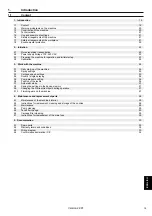
Page 3: ...itung der Maschine für den Betrieb und die erste Inbetriebnahme 3 7 Automatikmodus 3 3 Geschwindigkeitseinstellung 3 8 Programmspeicherung mittels den Funktionstasten 3 9 Pretreatment Flüssigkeit im laufenden Betrieb wechseln 3 10 Abschlussarbeiten an der Maschine 5 Dokumentation 4 Wartung und Austausch von Teilen 5 4 Konformitätserklärung CE 4 4 Pumpenreinigung 4 6 Carriage Filter Reinigung 4 3 W...

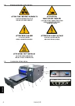
Page 4: ...UWAGA WYSOKIE NAPI ATTENTION HOT SURFACE ACHTUNG HEIßE OBERFLÄCHE ĄCA POWIERZCHNIA UWAGA GOR ATTENTION HAND CRUSH HAZARD ACHTUNG BEWEGLICHE TEILE UWAGA RUCHOME ELEMENTY ATTENTION MOVING ELEMENTS UWAGA NIEBEZPIECZEŃSTWO ZGNIECENIA DŁONI ACHTUNG QUETSCHGEFAHR DER HAND 1 3 Abbildung der Maschine DEUTSCH 2 3 4 5 6 7 8 9 10 12 13 11 14 1 Version 22 01 DEUTSCH ...

Page 5: ...der Einzel oder Doppelsprüheinstellung des Pumpendrucks und der Kalibrierung eingestellt werden Die Einstellungen der Maschine können für Material oder Job individuell eingestellt werden dazu kann folgendes Verfahren genutzt werden 1 5 Anwendungsbereich und Beispieleinstellung 05 1 6 Sicherheitsvorrichtungen der Maschine Hauptsicherung 6A Die Sicherung 6A befindet sich im hinteren Teil der Maschine...

Page 6: ...den Jeder Anwender ist zu einer sicheren Anwendung der Maschine verpflichtet den vom Produzenten vorgeschriebenen Sicherheitsvorkehrungen Folge zu reichen wie auch sich mit den zusätzlichen Risiken vertraut zu machen Der Gebrauch der Maschine weist gleichzeitig darauf hin dass der Anwender sich mit der Bedienungsanleitung bekannt gemacht hat und sich der eventuellen Risiken die bei derArbeit mit d...

Page 7: ...zu dass die Flüssigkeit problemlos abfliessen kann Der Schlauch darf nicht geknickt werden Machen Sie keine Schlaufe Stellen Sie den Tank nicht über den Auslass 1 Montieren Sie die Düsen nicht Foto 1 Tipp Wenn eine der Düsen nicht richtig funktioniert reinigen Sie die Düse im Ultraschallgerät und säubern Sie diese mit Druckluft Es liegt eine Ersatztdüse als Austausch bei 5 Halten Sie das Wassersymb...

Page 8: ...rd erneut aufgetragen 9 Falten Sie dasT Shirt und legen Sie es wieder auf die Waage Drücken Sie dieTaste Weiter 10 Wählen Sie den mit der Waage gemessenen Wert auf dem Display und bestätigen Sie mit Weiter Der Kalibrierungsvorgang ist beendet 5 Nehmen Sie dasT Shirt aus der Maschine falten Sie es neu und wiegen Sie es Drücken Sie Weiter auf dem Display 4 Falten Sie dasT Shirt und legen Sie es in d...

Page 9: ...te Länge Foto 2 Mit dem Button und wählen Sie den Sprühbereich aus Foto 3 3 3 Geschwindigkeitseinstellung Um die Geschwindigkeit der Carriage einzustellen drücken Sie die Taste Geschwindigkeit Foto 1 Diese Funktion ist nur aktiv wenn der Sprüh Modus auf Standard steht Stellen Sie die gewünschte Geschwindigkeit ein Foto 2 und speichern Sie die neue Einstellungen Foto 3 Wenn Sie die Geschwindigkeit ...

Page 10: ...stellungen Foto 4 Eine Veränderung des Druckes verursacht eine Änderung des Sprühwinkels der Düse Sie können den Druck von 30 bis 30 einstellen Ein zu niedriger Druck kann den Sprühwinkel so verkleinern dass die Fläche nicht gleichmäßig besprüht wird Ein zu hoher Druck wiederum wirkt sich negativ auf die Sprühbreite aus Der Druck muss so eingestellt werden dass der Sprühwinkel den genauen Wert der...

Page 11: ...ewünschten Tank aus indem Sie das Ventil Tank switch auf die Position Tank 1 oder Tank 2 stellen Nach jedem Wechsel spülen Sie die Schläuche 20 30 Sekunden mit der neuen Flüssigkeit Halten Sie dazu die PretreatmentTaste 20 30 Sekunden lang gedrückt 3 10 Abschlussarbeiten an der Maschine Das Gerät kann auf zweiArten ausgeschaltet werden Variante 1 ist die Taste der rechten Seite des Geräts Foto 1 V...

Page 12: ...eisenden Fett mit Hilfe eines Pinsels ein Foto 6 4 2 Austausch Reinigung und Lagerung der Düsen Zur Lagerung der Düsen verwenden Sie nur das SCHULZE Ultraschallgerät befüllt mit PRETREATcleaner Die Düsen dürfen nicht trocken gelagert werden oder im PRETREATmaker verbleiben Wechseln Sie in regelmäßigen Abständen mindestens 1 x pro Woche das alte Reinigungsmittel im SCHULZE Ultraschallgerät aus Weit...

Page 13: ... Sie das Gerät ausschalten und den Stromstecker aus der Steckdose ziehen Danach öffnen Sie dieAbdeckung der Sicherungen Foto 1 In Foto 2 sehen Sie 2 Sicherungen A B 4 5 Tankfilterwechsel Prüfen Sie den Tankfilter wenn Pretreatment oder Wasser nicht korrekt zu den Düsen läuft und tauschen Sie diesen gegeben falls aus Öffnen Sie die Seitenabdeckung des Geräts Der Filter befindet sich in den Tanks Fot...

Page 14: ...5 Dokumentation 5 1 Ersatzteile 807053 XXXXX1 XXXXX2 807055 807015 807016 803522 807094 XXXXX3 XXXXX4 XXXXX5 XXXXX6 XXXXX7 XXXXX8 XXXXX9 XXXX10 XXXX11 803524 14 Version 22 01 DEUTSCH ...

Page 15: ...807057 807132 807020 807026 807025 807030 807026 807019 807025 807025 807006 807100 807027 XXXX12 803422 XXXX13 XXXX14 XXXX15 XXXX16 801809 XXXX17 XXXX18 XXXX14 807034 Version 22 01 15 DEUTSCH ...

Page 16: ...older PRA TEX 000270 Uchwyt na kabel USB 807094 Filtr PRE807094 Filter Filter XXXX10 Tankbehälter Tank PRA TEX 000266 Zbiornik 5L złączka PUL 08 filtr do PRE 5 MAX XXXX11 Verbindungsstück Connecting piece Złączka PUL 08 MAT2 BIB 000220 807016 k Zbiornik 5L złączka PUL 06 filtr PRE807016 Tankbehälter Tan 807015 Filtr MAT1 POZ 001418 Filter Filter 807019 Przewód U 06040 BK dł 6m PRE807019 Kabel Cable ...

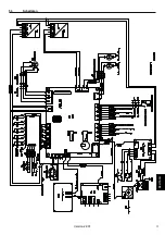
Page 17: ...5 3 Schaltplan Version 22 01 17 DEUTSCH ...

Page 18: ...SO 12100 2012 PN EN 60204 1 2018 12 PN EN 61000 6 3 2008 A1 2012 Angewendet Qualitätssystem testing report 2022 PN EN ISO 13850 2016 03 PN EN IEC 6300 2019 01 Reda den 22 02 2022 Andrzej Romanik Sarirstraße 5 Die technischen Konstruktionsunterlagen TCF für dieses Produkt sind bei dem oben genannten Hersteller hinterlegt Walter Schulze GmbH Für die technische Dokumentation ist Romanik Andrzej Roman...

Page 19: ...up 3 Work with the machine 3 1 Daily start up of the machine 3 3 Carriage speed settings 3 5 Pump pressure setting 3 7 Automatic mode 3 6 Position of the textile 3 10 Finishing work on the machine 4 Maintenance and replacement of parts 4 2 Instructions for replacement cleaning and storage of the nozzles 4 3 Maintenance 4 4 Pump cleaning 4 5 Tank filter change 4 6 Carriage filter cleaning 4 7 Instruc...

Page 20: ...ANNUNG ĘCIE UWAGA WYSOKIE NAPI ATTENTION HOT SURFACE ACHTUNG HEIßE OBERFLÄCHE ĄCA POWIERZCHNIA UWAGA GOR ATTENTION HAND CRUSH HAZARD ACHTUNG BEWEGLICHE TEILE UWAGA RUCHOME ELEMENTY ATTENTION MOVING ELEMENTS UWAGA NIEBEZPIECZEŃSTWO ZGNIECENIA DŁONI ACHTUNG QUETSCHGEFAHR DER HAND 1 3 Construction of the machine DEUTSCH 2 3 4 5 6 7 8 9 10 12 13 14 1 ENGLISH 11 ...

Page 21: ... by adjusting the speed single or double spray setting pump pressure and calibration The machine settings can be adjusted individually for material or job the following technique can be used for this purpose Barcode scanner 1 5 Use and example of settings 21 Main fuse 6A 12 24 VAC Installation All control elements of the machine are supplied with a safe voltage not higher than 24V Voltage of 100 2...

Page 22: ... care and be alert to avoid other dangerous situations The machine should be operated in accordance with the manufacturer s recommendations to avoid risks The machine complies with the essential requirements laid down in regulation for machines Above information has been worked out in accordance with the standards PN EN 12100 2012 The machine is constantly upgraded in order to improve its safety A...

Page 23: ...ce the tank over the outlet 5 Press and hold the water button for 10 30 sec pictures 6 7 Then press and hold the pretreatment button for 10 to 30 seconds All tubes must be free of air bubbles picture 8 Press Ready and then Confirm execution on the touch screen 4 Turn on the machine pictures 4 5 Set the language location date and time on the machine 6 Install the nozzles picture 9 and press Start on...

Page 24: ... the machine press the field Speed Ref amount on the display picture 1 and then Calibration picture 2 To carry out the calibration you will need a L XL size t shirt a scale with an accuracy of 1g and a set of new nozzles Make sure that there is sufficient fluid in the tanks Press STARTand then In order to check the amount of pretreatment to be applied to the t shirt a calibration must be carried o...

Page 25: ...e 5 4 The printing area can also be set by switching individual zones on or off picture 6 3 3 Carriage speed settings To change the speed of the carriage click on the Speed field picture 1 This function is only active when the spray mode is set to standard Adjust the carriage speed as required picture 2 and save the new settings picture 3 By increasing the speed of the carriage the amount of preco...

Page 26: ...ssure affects the shape of the spray from the nozzles You can set the pressure between 30 and 30 Too low pressure can reduce the spraying angle so that the surface is not sprayed evenly Too high pressure in turn has a negative effect on the spraying width The pressure must be adjusted so that the spray angle reaches the exact value of the nozzles You can choose between 65 and 80 nozzles PRETREATma...

Page 27: ...ecoating to be used switch the Tank switch valve to the position tank 1 or tank 2 After each change rinse the hoses with the new liquid for 20 30 seconds To do this hold down the pretreatment button for 20 30 seconds 3 10 Finishing work on the machine The device can be switched off in two ways Option 1 is the button on the right side of the machine picture 1 Option 2 is the button Switch off in th...

Page 28: ...protects the rails from the damaging effects of precoating 4 2 Instructions for replacement cleaning and storage of the nozzles 4 2 1 Replacement of the nozzles 1 Open the front cover picture 1 2 Turn the nozzle cap to the left picture 2 and remove it 3 Place a new nozzle and fix it in the machine For more details see chapter 3 1 1 The nozzle may be cleaned in an ultrasonic cleaner picture 3 7 Ins...

Page 29: ...f the machine Pull both fuses out of the holder picture 3 Insert fuse B in place of fuseAand close the fuse holder A B 4 5 Tank filter change If precoating or water does not flow smoothly to the nozzles check the filter and replace it if necessary Open the side cover of the unit The filters are located in the tanks picture 1 Remove the hose from the tank picture 2 and replace the filter picture 3 4...

Page 30: ...5 Documentation 5 1 Spare parts 807053 XXXXX1 XXXXX2 807055 807015 807016 803522 807094 XXXXX3 XXXXX4 XXXXX5 XXXXX6 XXXXX7 XXXXX8 XXXXX9 XXXX10 XXXX11 803524 Version 22 01 30 ENGLISH ...

Page 31: ...807057 807132 807020 807026 807025 807030 807026 807019 807025 807025 807006 807100 807027 XXXX12 803422 XXXX13 XXXX14 XXXX15 XXXX16 801809 XXXX17 XXXX18 XXXX14 807034 ENGLISH 31 Version 22 01 ...

Page 32: ...l Cable 807015 Filtr MAT1 POZ 001418 Filter Filter XXXXX5 Touch Display komplett Display set świetlacz dotykowy kompletny do PRE 5 MAX PRA TEX 000264 Wy XXXX11 Verbindungsstück Connecting piece Złączka PUL 08 MAT2 BIB 000220 807026 Złączka PT 06 01 MAT2 PO 001262 Verbindungsstück Connecting piece XXXX12 Leitung Tube Przewód fi 8 mm 3m PRA TEX 000271 807020 Cewka 12V MAT2 PO 001055 Spule Coil 807006...

Page 33: ...5 3 Wiring diagram Version 22 01 ENGLISH 33 ...

Page 34: ...omanik pl Directive 2011 65 EU and Directive 2015 863 is compliant with the specifications of the followings EC directives Low Voltage 2014 35 EU PN EN IEC 6300 2019 01 ul Przemysłowa 10 used norms and technical specifications Polen PN EN 60204 1 2018 12 Andrzej Romanik Machinery 2006 42 EC PN EN 61000 6 3 2008 A1 2012 Manufacturer Applied quality system testing report 2022 Romanik Andrzej Romanik S...

Page 35: ...nych 3 6 Pozycja koszulki 5 2 Warunki gwarancji 3 3 Ustawienie prędkości wózka 5 4 Deklaracja zgodności CE 3 7 Tryb automatyczny 4 2 Instrukcja wymiany czyszczenia i przechowywania dysz 4 6 Filtr na karetce 5 1 Spis części wymiennych 4 1 Konserwacja wnętrza maszyny 3 9 Wybór zbiornika 4 Konserwacja i wymiana części 3 4 Podwójny pojedynczy zadruk 4 5 Instrukcja wymiany filtra 5 Dokumentacja 3 10 Zak...

Page 36: ...PANNUNG ĘCIE UWAGA WYSOKIE NAPI ATTENTION HOT SURFACE ACHTUNG HEIßE OBERFLÄCHE ĄCA POWIERZCHNIA UWAGA GOR ATTENTION HAND CRUSH HAZARD ACHTUNG BEWEGLICHE TEILE UWAGA RUCHOME ELEMENTY ATTENTION MOVING ELEMENTS UWAGA NIEBEZPIECZEŃSTWO ZGNIECENIA DŁONI ACHTUNG QUETSCHGEFAHR DER HAND 1 3 Budowa maszyny DEUTSCH 2 3 4 5 6 7 8 9 10 12 13 14 1 Wersja 22 01 11 ...

Page 37: ...tawienie pojedynczego lub podwójnego spryskiwania ciśnienie pomp oraz kalibrację Ustawienia maszyny należy dostosować każdorazowo do projektu i stosowanych materiałów korzystając z poniższej metody skaner kodów kreskowych 1 5 Zastosowanie i przykładowe ustawienia 37 POLSKI W celu zapewnienia maksymalnego bezpieczeństwa pracy urządzenie PRETREATmaker 5 MAX zostało wyposażone w kilka niezależnych za...

Page 38: ...zagrożenia dla osób obsługujących maszynę lub przechodzących obok niej W przypadku uszkodzenia przewodów zasilających należy przerwać pracę wyłączyć maszynę wyciągnąć wtyczkę zasilającą z sieci i skontaktować się z serwisem Nie wykonywać żadnych napraw we własnym zakresie nie odkręcać pokryw w trakcie pracy Podczas prac konserwacyjnych wtyczka zasilająca maszynę musi być wyciągnięta z gniazda zasi...

Page 39: ...owka Jeśli jedna z dysz nie działa prawidłowo należy ją wyjąć i umieścić w myjce ultradźwiękowej a następnie wyczyścić sprężonym powietrzem Do maszyny dołączona jest jedna zapasowa dysza 3 Podłączyć zbiornik ściekowy zdjęcie 3 Przyciąć wężyk do pożądanej długości tak aby płyn swobodnie spływał do zbiornika Nie zaginać wężyka Nie robić pętli Nie umieszczać zbiornika powyżej wylotu 1 Nie instalować ...

Page 40: ...szynie Nacisnąć Dalej Natrysk Nastąpi nanoszenie podkładu na koszulkę 3 Wytarować wagę po zważeniu koszulki wcisnąć przycisk tara na wadze Nacisnąć dalej na wyświetlaczu 7 Wytarować ponownie wagę z koszulką z naniesionym podkładem i wcisnąć Dalej 9 Złożyć koszulkę w kostkę i umieścić ją ponownie na wadze Wcisnąć przycisk Dalej Proces kalibracji został zakończony 10 Wybrać zważoną ilość naniesioneg...

Page 41: ...a rozpocząć się nanoszenie podkładu zdjęcia 4 5 4 Obszar zadruku można również ustawić włączając lub wyłączając poszczególne strefy zdjęcie 6 3 3 Ustawienie prędkości wózka Aby zmienić prędkość ruchu wózka należy nacisnąć na pole Prędkość zdjęcie 1 Ta funkcja jest aktywna tylko gdy wybrany jest standardowy tryb nanoszenia Dostosować prędkość wózka według potrzeb zdjęcie 2 i zapisać nowe ustawienia...

Page 42: ...tawienia zdjęcie 4 Zmiana ciśnienia wpływa na kształt strumienia płynącego z dysz Ciśnienie można ustawić w zakresie od 30 do 30 Zbyt małe ciśnienie może spowodować zmniejszenie kąta rozpylania przez co powierzchnia nie będzie spryskiwana równomiernie Z kolei zbyt wysokie może skutkować nadmiernym rozpyleniem precoatingu na ściankach urządzenia Do wyboru są dysze o kącie 65 i 80 PRETREATmaker 5 or...

Page 43: ...podkładem który ma być używany należy przełączyć zawór Tank switch na pozycję Tank 1 lub Tank 2 Po każdej zmianie należy przepłukać pompę nowym płynem przez około 20 30 sekund W tym celu należy wcisnąć i przytrzymać przycisk Pretreatment przez około 20 30 sekund 3 10 Zakończenie pracy przy maszynie Maszynę można wyłączyć na dwa sposoby Sposób pierwszy to użycie przycisku znajdującego się z prawej ...

Page 44: ...uszczone Prowadnice nie mogą pozostać suche Prowadnice należy nasmarować tłuszczem odpornym na wodę używając pędzla zdjęcie 6 4 2 Instrukcja wymiany czyszczenia i przechowywania dysz 2 Wykręcić kołpak z dyszą i go zdjąć zdjęcie 2 3 Uzupełnić myjkę ultradźwiękową płynem PRETREATcleaner do górnej granicy 6 Wyjąć dysze i przepłukać wodą Na dyszach nie powinny zostać żadne pozostałości płynu czyszcząc...

Page 45: ... Wyciągnąć oba bezpieczniki z uchwytu zdjęcie 3 Włożyć bezpiecznik B w miejsce bezpiecznikaAi ponownie zamknąć uchwyt bezpiecznika A B 4 5 Instrukcja wymiany filtra W przypadku gdy precoating bądź woda nie będą płynnie leciały do dysz należy sprawdzić filtr i w razie potrzeby go wymienić W tym celu należy otworzyć boczną pokrywę urządzenia Filtry znajdują się w zbiornikach z cieczą zdjęcie 1 Ze zbi...

Page 46: ...5 Dokumentacja 5 1 Spis części wymiennych 807053 XXXXX1 XXXXX2 807055 807015 807016 803522 807094 XXXXX3 XXXXX4 XXXXX5 XXXXX6 XXXXX7 XXXXX8 XXXXX9 XXXX10 XXXX11 803524 Wersja 22 01 46 POLSKI ...

Page 47: ...807057 807132 807020 807026 807025 807030 807026 807019 807025 807025 807006 807100 807027 XXXX12 803422 XXXX13 XXXX14 XXXX15 XXXX16 801809 XXXX17 XXXX18 XXXX14 807034 47 POLSKI Wersja 22 01 ...

Page 48: ...XXX8 USB Kabelhalterung USB cable holder PRA TEX 000270 Uchwyt na kabel USB XXXXX9 Tankb älter Tank PRA TEX 000265 eh Zbiornik 10L złączka PUL 08 filtr do PRE5 MAX 807094 Filtr PRE807094 Filter Filter XXXX10 Tankbehälter Tank PRA TEX 000266 Zbiornik 5L złączka PUL 08 filtr do PRE 5 MAX 803524 Złączka PUL 06 MAT2 PO 000696 Verbindungsstück Connecting piece 807015 Filtr MAT1 POZ 001418 Filter Filter 8...

Page 49: ...5 3 Schemat połączeń 49 POLSKI Wersja 22 01 ...

Page 50: ...dotyczy niniejsza deklaracja jest zgodny z odpowiednimi dyrektywami PN EN ISO 12100 2012 PN EN 60204 1 2018 12 PN EN 61000 6 1 2019 03 PN EN 61000 6 3 2008 A1 2012 PN EN IEC 6300 2019 01 Reda dnia 22 02 2022 r Zastosowano system jakości testing report 2022 Właściciel firmy Andrzej Romanik Dokumentacja techniczna TCF dla tego wyrobu jest przechowywana w podanej wyżej siedzibie producenta Podmiot upo...

Page 51: ......

Page 52: ......

Reviews: