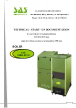
SAS GRO-ECO Technical - Start - Up Documentation Download Page 6


6


  grateless, self-cleaning furnace in the from on the cast iron retort of goblet 

shape 

  fan blowing the air into the chamber – retort 

  electronic temperature controller. 

 
The fuel for combustion process is transported by means of a screw feeder from the 
fuel hopper placed by the side of  boiler.  
All  processes  leading  to  fuel  combustion    together  with  the  air  delivered  by  blow-in 
fan take place in the iron cast retort. Above the coal burner an iron cast deflector in 
placed. The deflector  radiator plate deflecting  heat  radiation onto a glow  in order to 
make  combustible  gases  be  burner  completely  and  distribute  fumes  into  the  heat 
exchanger  uniformly.  The  cinder  which  has  been  formed  in  the  final  phase  of 
combustion process in moving towards the rim of the retort, and then drop down into 
an ash pan chamber. For easier maintenance the chamber is provided with a drawer 
pullout type. 
Due to its efficiency, the combustion chamber burns such a quantity of fuel, which is 
necessary  to  obtain  the  temperature  set  on  the  controller.  The  controller  constantly 
measures  the temperature of  water  boiler.  Depending on the  results, it  controls fuel 
feeder  and  ventilator.  At  the  same  time  the  controller  operates  a  circulation  pump 
(provided  a  heating  installation  is  equipped  with  such  pump).  Detailed  design, 
functioning  and  operation  description  of  the  controller  is  attached  to  this  controller 
manual. 
The  boiler’s  advantage,  is  a  simple  operation  relaying  on  periodic  coal  bunker 
refueling  (the  fuel  bunker)  and  cinder  removing  from  the  ash  drawer  with  no 
requirement  to  stop  the  boiler.  Once  boiler  is  fired  up,  it  does  not  call  for  further 
service, and its operation may be practically continuous in the entire heating season. 
Boiler  may  be  also  use  beyond  heating  season  in  the  configuration  with  hot  utility 
water boiler. 
Tree- duct gas channel construction renders full utilization of gasses heat. In addition, 
the upper part of combustion chamber is closed with a water jacket. 
Gases are transferred into a chimney trough the smoke conduit situated at the back 
of a boiler. The smoke conduit is equipped with smoke throttle, with in case in to high 
chimney  draught  allows  for  its  throttling.  On  the  smoke  conduit  sidewall  there  is 
washout  whole.  Combustion  chamber  door,  and  ash  box  door  are  placed  on  the 
boiler’s front. For periodic cleaning operations and also for firing up a boiler, the retort 
may be accessed through furnance door.    
In  the  upper  part  of  boiler,  under  the  cover,  there  is  a  flap  of  upper  washout  hole 
cover.  It  renders  easy  access  to  perform  cleaning  operation  of  the  heat  exchanger 
cassettes. Lateral washout door are used for dust removing if accumulated.  
To  the  upper  part  of  the  heat  exchanger  a  hot  water  connector  is  welded.  To  the 
lower  part  of  it,  on  the  back  wall,  a  return  water  connector  is  welded.  Blowdown 
connection is placed on the boiler’s lateral wall. 
The  entire  constructions  is  wrapped  with  insulation  material,  a  mineral  wool,  which 
fills the space between a head exchanger and boiler’s casing.  


Summary of Contents for GRO-ECO

Page 1: ...K I 28 100 Busko Zdr j Owczary ul Przemys owa 3 Phone 48 41 378 46 19 Fax 48 41 370 83 10 TECHNICAL START UP DOCUMENTATION of water boilers for heating installations SAS GRO ECO type adopted for black...

Page 2: ...o electrical installation 10 7 Operation and exploitation guidelines 10 7 1 Filling with water 10 7 2 Firing up and functioning of a boiler 10 7 2 1 Firing up and functioning of a boiler in automatic...

Page 3: ...3...

Page 4: ...4...

Page 5: ...lculated feeding water temperature does not exceed 85 C and working pressure does not exceed 1 5 bar Required gases draught pressure after a boiler is 0 30 0 55 mbar depending on boiler s power These...

Page 6: ...antage is a simple operation relaying on periodic coal bunker refueling the fuel bunker and cinder removing from the ash drawer with no requirement to stop the boiler Once boiler is fired up it does n...

Page 7: ...g coal should not tend to stick when burner Volatile particles content 30 40 It is recommended to use coal which is prone to agglomeration coking although it is good caloric properties higher losses o...

Page 8: ...OTE Employing of mechanical blow out ventilation is unacceptable The boiler room should be provided with day and artificial lighting 6 2 BOILER ARRANGEMENT Special foundation for boiler is not require...

Page 9: ...required to apply flue insert however in year round exploitation it is recommended to provide heating to the hot utility water container 6 4 CONNECTING BOILER TO HEATING INSTALLATION The boiler should...

Page 10: ...y allowing the air residing in the installation to be removed It is accomplished when water is going out of overflow pipe When filling the heating system installation with water it is recommended to l...

Page 11: ...el quality may cause the boiler to burn out If the fire is out during up phase the furnace should be cleaned and boiler s channels ventilated and the whole starting procedure must be repeated Once boi...

Page 12: ...sition of the gate valve At the same time the controller operates the heating system circulation pump if such is provided Heat requirement in the heat installation is varying due to changing outdoor c...

Page 13: ...Required chimney draught mbar 0 30 0 45 9 Exhaust temperature C 90 210 10 Recommended heating water working temp C 60 80 11 Maximal allowable working temperature C 85 12 Maximal allowable operating pr...

Page 14: ...chimney draught mbar 0 55 9 Exhaust temperature C 90 210 10 Recommended heating water working temp C 60 80 11 Maximal allowable working temperature C 85 12 Maximal allowable operating pressure bar 1 5...

Page 15: ...turn water connector pipe 13 blowdown connection 14 lateral washout hole door 15 blowing fan 16 feeder drive mechanism 17 deflector 18 retort burner 19 water jacket 20 ash box 21 safety valve 22 aerat...

Page 16: ...controller 11 smoke conduit cleaning hole 12 smoke conduit 13 smoke throttle 14 safety valve 15 upper washout hole cover 16 hot water connector pipe 17 fuel storage bin 18 blowing fan 19 feeder drive...

Page 17: ...hed or when switching off the boiler is scheduled the controller should be then switched off and the glowing batch should be removed from retort and push into ash box chamber Once boiler is out and co...

Page 18: ...lung if its amount is excessive 3 Control fuel level in the hopper 4 Check the hopper and shielding pipe against coal dust accumulation if required remove it 5 Check if air nozzles are not damaged and...

Page 19: ...en temperature and pressure rise installation valves closed open the valves pressure vessel frozen heat the pressure vessel Water licking out of boiler so called boiler s sweating this is natural proc...

Page 20: ...llic sensor is faulty If temperature of 95 C is exceeded cutting off power supply to blow in fan and fuel feeder is executed FUEL BUNKER PROTECTION A controller is additionally protected against flame...

Page 21: ...components mounted on the boiler and produced by other manufacturers controller blowing fan safety valve automatic fuel delivery system details of the manufacturer warranty 5 Warranty does not cover...

Page 22: ...eserves the right to introduce changes in the construction of the product for modernization purpose Such changes may not be reflected in hereby documentation however basic described properties of the...

Page 23: ...23 SERVICE REPAIRS...

Page 24: ...erature boiler of SAS GRO ECO type installed and operated in pursuance of Technical Start Up Documentation Boiler no Heating capacity Heated surface Year of manufacture Manufacturer signature and stam...

Reviews: