background image

17

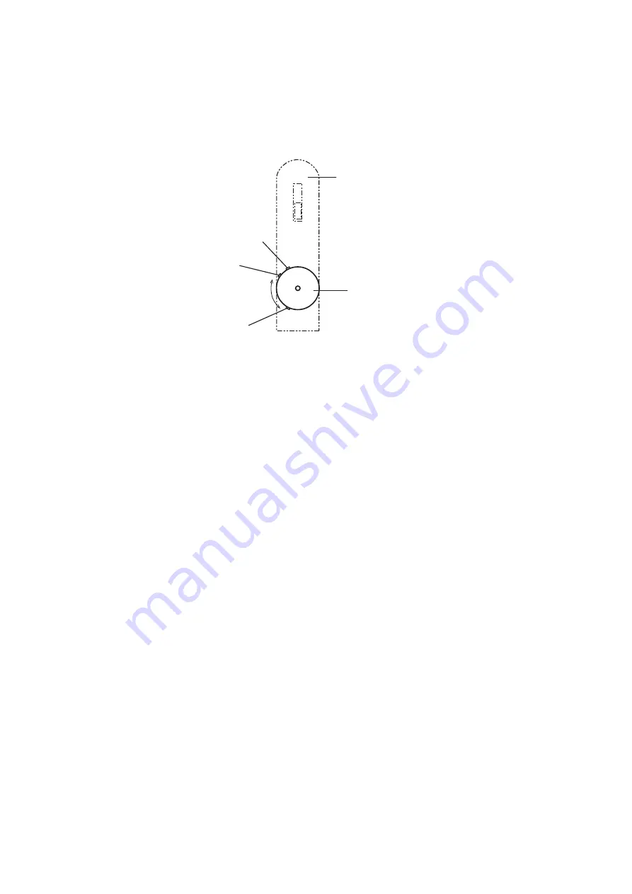
Adjust  airflow  rate  by  turning  the  airflow  control  valve  in  the  range  MIN  position  to  

MAX  position  shown  in  Figure  9.   Turning  it  over  MAX  position  to  STOP  position  

reduces  the  airflow  rate  due  to  valve  structure.

3.  HOW  TO  POLISH  A  WORK  PIECE  WITH  THE  FLEXIBLE  POLISHING  PAD

     When  the  polisher  rotation  gets  stable  after  the  start,  begin  the  polishing  operation,  Put  

     the  flexible  polishing  pad  slowly  on  the  face  to  be  polished  when  it  comes  in  touch  with  

     a  work  piece.   Too  much  force  to  the  pad  would  damage  the  work  piece  and  cause  

     quick  worn-out  of  the  pad,  and  would  not  be  an  efficient  polishing.

     The  efficient  polishing  depends  on  many  elements,  characteristics  of  work  piece,  the  

     flexible  polishing  pad,  pressure  between  the  flexible  polishing  pad  and  work  piece,  water  

     flow  rate,  skill  of  operator  and  polisher  speed.

     The  operator  would  have  an  experience  of  optimum  water  flow  rate.   Contact  of  polisher  

     speed  is  utilized  by  airflow  control  value  ( see  Figure  1,  page  6 )  The  optimum  polishing  

     speed,  therefore,  could  not  be  specified  in  this  instruction  manual  due  to  too  many  

     elements.

     Relation  of  r/min  and  compressed  air  pressure  is  shown  in  Figure  5  in  page  8.   The  

     operator  would  have  an  experience  of  optimum  polisher  speed.

4.  CAUTIONS  IMMEDIATELY  AFTER  USE

     After  the  polishing  operation,  turn  OFF  the  switch  lever  and  place  the  polisher  on  floor  

     ensuring  that  its  rotation  is  completely  stopped.   Failure  to  do  so  could  cause  accidents.   

     Inordinate  impact  to  the  polisher  body  could  result  in  tear  or  crack  of  the  polisher  and  

     the  flexible  polishing  pad.   Handle  them  with  good  care. 

Switch  Lever

Stop

Max.

Min.

Airflow  Control  Valve

Figure  9  Airflow  Control  Valve

Summary of Contents for PA-2

Page 1: ... accident prevention and safety operation before use carefully read this instruction manual and follow the instructions warnings and cautions given therein Further store this instruction manual at a place where operator and maintenance staff can access thereto easily anytime as necessary ...

Page 2: ......

Page 3: ...ndling that is failure to follow the cautions and instructions given in this instruction manual could cause injuries of operator or otherwise physical damage DECLARATION DECLARED DUAL NUMBER NOISE EMISSION VALUES IN ACCORDANCE WITH ISO 4871 Measured A weighted sound power level LWA in decibels Uncertainty KWA in decibels Measured A weighted emission sound pressure level LpA at the operator s posit...

Page 4: ...S KNOWLEDGE TO USE THIS POLISHER 6 POLISHING AT HIGH WORKPLACE 7 ELECTRICAL INSULATING NAME OF PARTS 6 STANDARD ACCESSORIES 6 OPTIONS 7 SPECIFICATIONS 8 APPLICATION 8 CHECK ITEMS BEFORE OPERATING 9 PREPARATIONS BEFORE OPERATING 10 HOW TO POLISH 15 AFTER USE 18 MAINTENANCE AND CHECK 19 TROUBLESHOOTING 19 DISPOSAL OF POLISHER 19 CONTACT LIST 20 EC Declaration of Conformity 21 ...

Page 5: ... control valve under OFF condition WARNING CAUTION 2 OPERATIONAL ENVIRONMENT DO NOT ALLOW ANY OTHER OPERATORS TO ACCESS TO THE POLISEHR Do not allow any other operators except specific operators to access to the work place Particularly be careful not to allow children to access the working area CAUTION AGAINST EXPLOSION AND FIRE Do not use the polisher absolutely in potentially explosive atmospher...

Page 6: ...on the nameplate of the polisher and described in SPECIFICATIONS in page 8 MOUNT A FLEXIBLE POLISHING PAD DESIGNED FOR THIS POLISHER This polisher is for polishing operation fitted with flexible polishing pad and various soft materials or felt pad for polishing of surface like our DIA CERAMICA CAUTION THIS POLISHER SHALL BE USED FOR WET MODE OPERATION Using dry mode pad will cause extremely higher...

Page 7: ...ause electrocution Comply with the current legislations and regulations relating to noise Plant or shop which uses the polisher must use the polisher with the condition below the noise level regulated by the local administrative authority not to disturb neighbors A sound shield is recommended to use as necessary Attentive points ...

Page 8: ...sories 1 Water splash skirt Normal size 1pc Bigger size 1pc 2 Hose fittings Hex Nipple G1 4 1pc 3 Air hose 7X10 1pc 4 Couplers for water 1pc 5 Flexible water hose 1pc 6 Exhaust air duct hose 1pc 7 Hose clamp 1pc 8 Wrench 22mm for spindle 1pc 26mm for rubber pad 1pc 9 Grip bar 1pc 10 Motor oil 30mm3 1pc ISO VG46 or DIN51502DL46 11 Spacer for M14 or M16 depending on spindle size 1pc 1 2 3 4 5 6 7 8 ...

Page 9: ...ns TABLE 2 RUBBER PAD TABLE 3 FAMILY OF DIA CERAMICA DIA CERAMICA FLEXIBLE POLISHING PAD V series Vitrified bond M series Metal bond R series Resinoid bond BUFF series TSUYA series 60V 150V 300V 60M 150M 300M 150R 300R 500R 1000R 2000R 3000R BUFF BLACK BUFF WHITE TSUYA BLACK TSUYA WHITE Numbers represent mesh size grid size of grain contained in DIA CERAMICA respectively RUBBER PAD Nominal diamete...

Page 10: ...ures and flat surfaces of marble granite and terrazzo Relation of r min and Compressed Air Pressure only reference Rated no load speed at air pressure of 0 6MPa Mass weight Maximum operating pressure of compressed air Consumption of compressed air 3 890r min min 1 1 2kg 0 6MPa 0 42m3 min at temperature 20 and atmospheric pressure r min 5000 4000 3000 2000 1000 0 0 40 0 45 0 50 0 55 0 60 0 65 MPa ...

Page 11: ... is not left on the polisher CAUTION Ensure the following items before operating 1 KEEP IN ORDER OF WORKPLACE Keep the workplace in order before the start of polishing operation When there is dust around it would be flown by the exhaust air conducted through the exhaust air duct hose see Figure 3 and 6 page 6 and 11 Flying dust would cause respiratory diseases at throat and lungs 2 COMPRESSOR CAPA...

Page 12: ...ccording to TABLE 1 in page 6 2 Install the water splash skirt on the polisher body while expanding the clamping mouth see Figure 4 page 7 of water splash guard from inside with fingers so that the clamping mouth fits onto the circumference groove see Figure 2 page 6 on the polisher body 3 PREPARE THE POLISHER CAUTION CHECK FOREIGN PARTICLES Foreign particles in the motor could cause rotating fail...

Page 13: ...ng ensure that the air hose is not disconnected even if adding tension load thereto 3 Insert the exhaust air duct hose in the end case and clamp it with the hose clamp Figure 6 Connections of Hoses 4 TAKE NECESSARY MEASURES In terms of environment health and safety codes take the necessary measures properly when operating the polisher referring to DECLARATION in page 1 Exhaust Duct Upper Hose Nipp...

Page 14: ...ile paying attention not to lose the spacer 5 For replacing follow the procedure of 5 1 MOUNTING OF RUBBER PAD AND FLEXIBLE POLISHING PAD 6 CONNECT THE AIR HOSE TO THE COMPRESSOR 1 Make sure to clean out the fitting part see Figure 3 page 6 to remove dust and foreign particles so that dust and or any foreign particles do not contaminate inside of hoses Contamination possibly damages the air motor ...

Page 15: ...ING CONNECT THE AIR HOSE SECURELY Disconnection of the air hose during operation could result in hazardous whipping of the air hose Connect the air hose securely In addition when connecting the air hose to the compressor ensure the switch lever is locked at OFF position DO NOT TOUCH THE ROTATING PARTS Do not access to the flexible polishing pad and the rotating parts while the polisher is in runni...

Page 16: ...es at the speed specified by the manufacturer of flexible polishing pad 2 Close the airflow control valve fully and open again slightly 3 Turn ON the switch lever 4 Adjust the airflow control valve slowly until it opens completely little by little 5 With this condition make test run for the specified period of test run time described below in this page Continuing the test run and or polishing oper...

Page 17: ...ile the polisher is in running MAKE TEST RUN BEFORE POLISHING When the polisher has reached the rotations for use after start ensure no inordinate noise and or vibration For the test run time refer to TEST RUN TIME in page 14 Polishing without test run could cause injuries FIX FIRMLY THE WORK PIECE USING CLMAP AND OR EQUIVALENTS Failure to be fixed could cause an incidental drop of the work piece ...

Page 18: ...TLY Failure to do so would possibly result in dry mode operation due to luck of water causing fire and respiratory diseases at throat and lungs 1 CONNECTION FOR WATER SUPPLY Connect the flexible water hose to the hose nipple on the polisher body see Figure 6 page 11 and to the water source Adjust the water flow rate by the water flow control valve so that the work piece and the flexible polishing ...

Page 19: ... flexible polishing pad and work piece water flow rate skill of operator and polisher speed The operator would have an experience of optimum water flow rate Contact of polisher speed is utilized by airflow control value see Figure 1 page 6 The optimum polishing speed therefore could not be specified in this instruction manual due to too many elements Relation of r min and compressed air pressure i...

Page 20: ...m heat oil and article with sharp edge CAUTION AFTER USE 1 DISCONNECT THE AIR HOSE 1 Close the stop valve on the compressor 2 Turn OFF the polisher by switch lever 3 Disconnect the air hose and exhaust air duct hose 4 Disconnect the flexible water hose from water source The flexible water hose does not need to be disconnected from the polisher body 2 EXECUTE AN ADEQUATE MAINTENANCE Execute an adeq...

Page 21: ...ent drain every time before use as necessary Oiling every time after use Cleaning every time after use Make sure each mounted screw is not loose and missed Operating the polisher with such screws could result in accidents Retighten the screws without fail The compressed air containing dust and condensed air could cause trouble of the polisher Completely drain out condensed water before storage Dus...

Page 22: ...667135 E mail info ske diamantwerkzeuge de RIEL SANWA SRL Address Via Gasparotto 11 21046 Malnate VA ITALY Tel 39 0 332 427375 Fax 39 0 332 426869 E mail riel riel it MANUFACTURER SANWA KENMA LTD Address 22 1 Kaminoyama Okubo cho Uji city Kyoto 611 0033 JAPAN Tel 81 0 774 41 6656 Fax 81 0 774 43 9201 Website http www sanwakenma co jp ...

Page 23: ...74 41 6656 Fax 81 774 43 9201 URL http www sanwakenma co jp Sanwa Kenma Ltd 2006 42 EC relating machinery It confirms that the listed equipment not annex IV equipment complies with the principal protection requirements of the directive To which this declaration relates complies with the provisions of following European Directives Applied Harmonized Standards Authorized Representative Signature Dat...

Reviews: