background image

Programming

The IntelliTeam Automatic Restoration System is a self healing or Fault Location, 
Isolation, and Service Restoration (FLISR) application. There are two types of IntelliTeam 
system restoration that can be implemented with the 6800 controls. The IntelliTeam SG 
Automatic Restoration System, the latest version, is configured with the S&C IntelliTeam® 
Designer software.

After the settings have been configured with IntelliTeam Designer they are automati-

cally pushed to the controls. See S&C Instruction Sheet 1044-570 for more details.

The IntelliTeam® II Automatic Restoration System, the previous version, is configured 

through the IntelliTeam screens in the IntelliLink software. See S&C Instruction Sheet 
1045-530, “6800 Series Automatic Switch Controls with IntelliTeam® SG Automatic  
Restoration System: 

Setup

” for more information.

IntelliTeam System 

Configuration

In some cases, the 6800 control will be used to sectionalize by detecting phase and 
ground faults. The setpoint values are on the 

Setup>General>Fault Detection

 screen. 

These settings define the fault. Currents on all three phases are monitored and compared 
with these setpoints.

Stand-Alone 

Programming

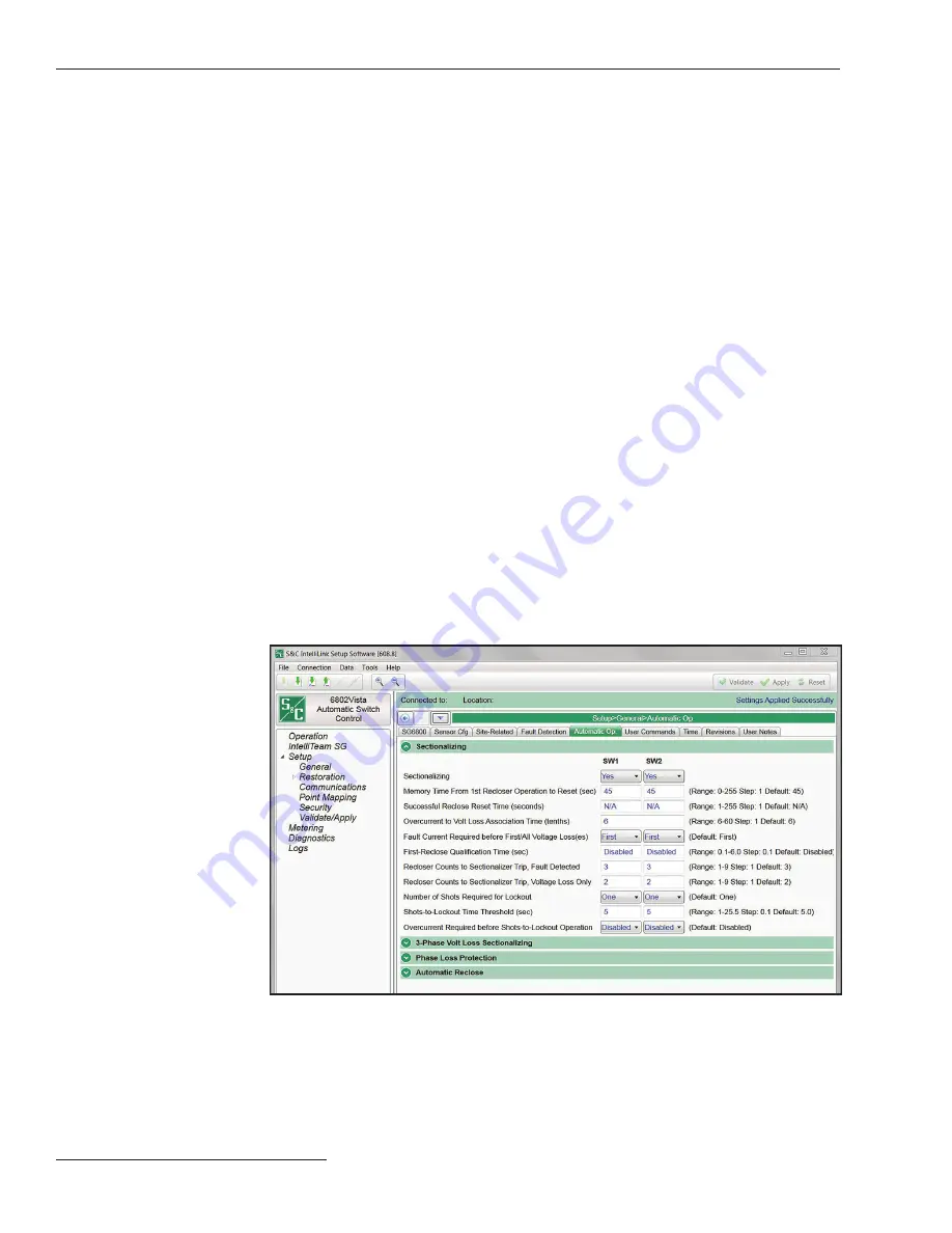
The 

Automatic Operation

 tab configures various automatic switch control operations. 

See Figure 12. For the 6802 and 6803 Automatic Switch Controls, configure most setpoints 
as separate values for Switch 1 and Switch 2. The switch control implements automatic 
operations based on the 

Sectionalizing Only

Phase Loss Protection Only

, or 

Sectionalizing plus Phase Loss Protection

 mode.

The 

Sectionalizing

 feature is based on the number of operations of an 

upstream or source-side breaker or recloser configured in the 

Recloser Counts to  

Sectionalize Trip, Fault Detected

 setpoint, while the 

3-Phase Volt Loss 

Sectionalizing 

feature is based on time. The 

Phase Loss Protection

 feature can be 

set to automatically operate the switch when the control detects loss of voltage on one 
or two phases.

Automatic Operation

Figure 12. The Setup>General>Automatic Operation>Sectionalizing screen. The 6802 control 
is shown.

16    S&C Instruction Sheet 1045-511

Summary of Contents for 6800 Series

Page 1: ...tch Control Configuration Log In to the Control 8 Software Screen Features 9 Validate Apply Screen 9 Security 10 General Setup 11 Sensor Configuration 12 Site Related Settings 13 Metering 13 Saving a Memory Snapshot 14 Communications 14 Programming Setpoint Files 15 IntelliTeam System Configuration 16 Stand Alone Programming 16 Automatic Operation 16 SCADA Point Mapping 17 January 6 2020 S C Elect...

Page 2: ...nent part of your 6800 Series Automatic Switch Control Designate a location where you can easily retrieve and refer to this publication The standard warranty contained in S C s standard conditions of sale as set forth in Price Sheets 150 and 181 applies to the 6800 Series Automatic Switch Control except that the first paragraph of the said warranty is replaced by the following 1 General The seller...

Page 3: ...ty of the 6800 Series Automatic Switch Control is contingent upon the installation configuration and use of the control or software in accordance with S C s applicable instruction sheets This warranty does not apply to major components not manufactured by S C such as batteries and communication devices However S C will assign to the immediate purchaser or end user all manufacturer s warranties tha...

Page 4: ...autions are not followed NOTICE NOTICE identifies important procedures or requirements that can result in product or property damage if instructions are not followed Following Safety Instructions If you do not understand any portion of this instruction sheet and need assistance contact the nearest S C Sales Office or S C Authorized Distributor Their telephone numbers are listed on S C s website sa...

Page 5: ...s Automatic Switch Control must be restricted only to qualified persons See the Qualified Persons section on page 2 2 SAFETY PROCEDURES Always follow safe operating procedures and rules 3 PERSONAL PROTECTIVE EQUIPMENT Always use suitable protective equipment such as rubber gloves rubber mats hard hats safety glasses and flash clothing in accordance with safe operating procedures and rules 4 SAFETY...

Page 6: ...hes in Remote Supervisory PME and PMH Pad Mounted Gear Remote Supervisory Vista and Vista SD Underground Distribution Switchgear and a variety of switches from other manufacturers 6800 controls can be operated in two states Local and Remote When set to the Remote state SCADA commands are permitted When set to the Local state SCADA commands are blocked and the 6800 control can be operated by the fa...

Page 7: ...trol faceplate Figure 2 The 6801 control Operation screen Automatic Restoration mode SCADA Control mode Automatic Operation mode Automatic Restoration mode SCADA Control mode Automatic Operation mode S C Instruction Sheet 1045 511 7 ...

Page 8: ...045 510 and 1045 540 have more information about the battery STEP 4 When the control is powered connect the computer to the control by a cable to one of the DATA PORTS on the faceplate Use a USB A to B cable or a serial cable Wi Fi can be used to connect to a control that has the Wi Fi option STEP 5 On the computer double click on the IntelliLink icon to launch the software STEP 6 Click on the Loc...

Page 9: ... configuration changes are validated and applied See Figure 5 on page 10 The Validate button evaluates settings in the buffer memory without applying them When changes are pending click on the Validate button to initiate a logical check of the pending changes for errors If the procedure detects an error or inconsistency it will be displayed in the Validation Result field The Apply button evaluates...

Page 10: ...s an Admin can make changes to this screen The User Group name can be changed for all groups except Admin and Viewer All passwords can be changed Passwords have no restrictions on characters and the max character limit is 12 A dialog box will open when the value to change is clicked on Changes do not take effect until the Apply button is clicked on in the Setup Validate Apply screen Security Figur...

Page 11: ...ral screen See Figure 7 The SG6800 tab configures name and location information for the switch control Name this control in the Device Name field and enter the location in the Device Location field These fields display to identify this control when you log in General Setup Figure 7 The Setup General SG6800 screen S C Instruction Sheet 1045 511 11 ...

Page 12: ...tion also stamped on each sensor Enter the information on this screen The 6801 controls do not have this card but the information is part of the data package provided with the Scada Mate switch Because the controls and switches are typically shipped separately it is important to make sure the information stays with the switch until it is pared with a control Sensor Configuration Figure 8 The Setup...

Page 13: ...omer voltage reporting The control uses this information when calculating kvars Set as either Phase to Neutral or Phase to Phase mode At the bottom of the screen are the Installation Voltage Current Phase Angle Offset settings The setpoints one for each voltage current phase allow installation dependent phase angle corrections The angle offsets are used to determine the Normal Current and Reverse ...

Page 14: ... name and location to save this snapshot STEP 3 Click on the Save button Saving a Memory Snapshot Remote com mu n icat ion ca n be con f ig u red for t he I ntel l iTea m SG Automatic Restoration System SCADA communications and IntelliLink Setup Software See Figure 11 Information supplied by the department that supports your field area net work is entered on this screen All the settings are define...

Page 15: ...a To save the stand alone setpoint values make sure the General and Communication check boxes are checked and the Restoration check box is unchecked Then click on the Save button b To save the team setpoint values click on the Profile Team x Setpoints option for the desired team Then click the OK button c To save all setpoint values including values for teams that may not have been configured clic...

Page 16: ...ground faults The setpoint values are on the Setup General Fault Detection screen These settings define the fault Currents on all three phases are monitored and compared with these setpoints Stand Alone Programming The Automatic Operation tab configures various automatic switch control operations See Figure 12 For the 6802 and 6803 Automatic Switch Controls configure most setpoints as separate val...

Page 17: ...x position of the selected point defining the order in which the points are returned to SCADA For a detailed description of the DNP point in your control refer to the appropriate S C instruction sheet on sandc com The DNP Points List instruction sheets have the prefix 1045 560 SCADA Point Mapping Figure 13 The Setup Point Mapping Status screen S C Instruction Sheet 1045 511 17 ...

Reviews: