


Installation
7
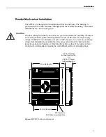
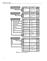
Connecting Power to the MP9311
On the MP9311, all power inputs are tied together and all commons (grounds) are
tied together. To connect power to the reader, apply 5 Vdc to all SCON1 power
input pin (16,18,20) and connect ground to all SCON1 common pin
(3,10,12,14,17,19). The SCON1 connector is rated to withstand a maximum
current of 1.0A per pin. Therefore, it is important that all power and ground pins be
connected to prevent reader damage. See Figure 4.
Figure 4–System Connector (SCON1) Power Connections
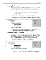
Connecting an RS-232/TTL Serial Link to the MP9311
On the MP9311, RS-232/TTL signals are located on pins 13 (TXD) and 15 (RXD).
The ground signals are connected as shown in Figure 4.
Figure 5–System Connector (SCON1) Serial Connections
1
2
5 Vdc
19
20
TXD
RXD
1
2
19
20
Summary of Contents for MP9311 Series
Page 1: ...User s Guide MP9311 Low Power UHF Reader Module THE POWER TO CHOOSE...
Page 6: ...MP9311 User s Guide iv...
Page 12: ...MP9311 User s Guide 6...
Page 34: ...MP9311 User s Guide 26...
Page 58: ...MP9311 User s Guide 50...
Page 59: ......


