


Circuit Operating Descriptions
13-21
Samsung Electronics
13-4 VCR Video
(1) Luminance Signal Recording System
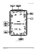
Fig. 13-21 Luminance Record Process
AV V IN
IC301 LA71750/30M
AUX V IN
TU V OUT
AGC
DET
VIDEO
AGC
F. B
CLAMP
6dB
AMP
QV/QH
INSERT
LPF
YNR Y/C
COMB
CCD
3 MHz
LPF
AMP
50
54
48
78
79
CANAL V IN
52
clock
data
68
69
AV VIDEO OUT
61
CANAL V OUT
63
FM
MOD
MAIN
EMPH
REC
FM EQ
W/D
CLIP
NL
EMPH
DETAIL
ENH
REC
CURRENT
AMP
SP H'D
CLAMP
46
43
FM
AGC
REC COLOR
88
94
+
SLP H'D
1) Outline
Fig. 13-21 shows the video signal recording system. Line input signal or tuner input signal is selected by Micom.
Input selection is done with the INPUT SELECT button on the remote. The input select control signal is supplied
to the pin 68(clock),69(data) of video IC from Micom IC.
The selected video input signal goes to pin 48(TUNER),50(AV), 52(CANAL), 54(AUX) of Lumi/Chroma processor
IC (IC301). And then it enters VIDEO AGC circuit. The gain of AGC circuit is controlled by AGC detector so that
the output is constant (approx. 2Vp-p). The output signal of AGC is clamped by the FBC(Feed Back Clamp) cir-
cuit. This signal appears at pin 26, after being amplified at the internal video amp and driver.
The output signal from the clamp circuit enter the detail enhancer circuit. In the detail enhancer circuit, the low
level high frequency video signal is emphasized to improve the original signals frequency characteristics.
onlinear emphasis circuit is employed to improve S/N and frequency response characteristics together with the
following main emphasis. Noise effects the FM wave at a higher frequency, so the S/N can be improved by
emphasizing the higher frequency before recording and by suppressing the play signal during demodulation.
The difference of non linear emphasis from main emphasis is that the emphasis characteristics change is depend-
ing on the input level. The gain of the emphasis circuit is inversely proportional to the level of the high frequency
component of the signal. That is, if the high frequency portion of the signal is low the main emphasis circuit will
amplify the signal.
Summary of Contents for DVD-V5450
Page 23: ...Reference Information 14 12 Samsung Electronics Fig 14 14 Mecha Timing Chart Kaiser II ...
Page 37: ...Reference Information 14 26 Samsung Electronics MEMO ...
Page 49: ...Product Specification 2 12 Samsung Electronics MEMO ...
Page 109: ...Operating Instructions 12 60 Samsung Electronics MEMO ...
Page 237: ...Troubleshooting 5 34 Samsung Electronics MEMO ...
Page 247: ...Exploded View and Parts List 6 10 Samsung Electronics MEMO ...
Page 263: ...Block Diagram 8 2 MEMO Samsung Electronics ...
Page 265: ...PCB Diagrams 10 2 Samsung Electronics 10 1 VCR Main PCB COMPONENT SIDE ...
Page 266: ...PCB Diagrams 10 3 Samsung Electronics CONDUCTOR SIDE ...
Page 267: ...PCB Diagrams 10 4 Samsung Electronics 10 2 DVD Main PCB COMPONENT SIDE ...
Page 268: ...PCB Diagrams 10 5 Samsung Electronics CONDUCTOR SIDE ...
Page 270: ...9 1 9 Wiring Diagram Samsung Electronics ...
Page 271: ...Wiring Diagram 9 2 MEMO Samsung Electronics ...