


Disassembly and Reassembly
4-13
Samsung Electronics
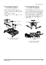
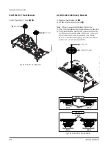
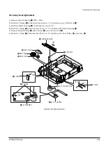
4-4-14 Gear Idle Ass’y Removal
1) Push the Lever Idle
Œ
in the direction of arrow
“A”, “B”.
2) Lift the Lever Idle
Œ
.
Assembly
:
1) Apply oil in two Bosses of Lever Idle
Œ
.
2) Assemble the Gear Idle
´
with the Lever Idle
Œ
.
Note
: When replacing the Gear Idle
´
, be sure to
add oil in the boss of Lever Idle
Œ
.
´
GEAR IDLE
"B"
Œ
LEVER IDLE
´
GEAR IDLE
"A"
HOOK "C"
Fig. 4-26 Gear Idle Ass’y Removal
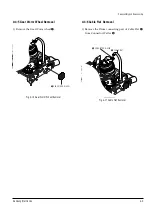
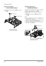
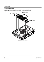
4-4-13 Lever Brake S, T Ass’y Removal
1) Release the Hook [A] and the Hook [B], [C] in the
direction of arrow as shown in Fig 4-25.
2) Lift the Lever S, T Brake Ass'y
Œ
,
´
with spring
brake
ˇ
.
Assembly
:
1)Assembly the Lever S Brake Ass'y
Œ
on the Main
Base.
2)Assembly the Lever T Brake Ass'y
´
with spring
brake
ˇ
.
Note
: Take extreme care not to be folded and
transformed Spring Brake at removing or reinstalling.
HOOK(A)
´
LEVER T BRAKE ASS`Y
Œ
LEVER S BRAKE ASS'Y
HOOK(B)
HOOK(C)
ˇ
SPRING BRAKE
Fig. 4-25 Lever Brake S, T Ass’y Removal
Summary of Contents for DVD-V5450
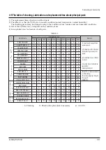
Page 23: ...Reference Information 14 12 Samsung Electronics Fig 14 14 Mecha Timing Chart Kaiser II ...
Page 37: ...Reference Information 14 26 Samsung Electronics MEMO ...
Page 49: ...Product Specification 2 12 Samsung Electronics MEMO ...
Page 109: ...Operating Instructions 12 60 Samsung Electronics MEMO ...
Page 237: ...Troubleshooting 5 34 Samsung Electronics MEMO ...
Page 247: ...Exploded View and Parts List 6 10 Samsung Electronics MEMO ...
Page 263: ...Block Diagram 8 2 MEMO Samsung Electronics ...
Page 265: ...PCB Diagrams 10 2 Samsung Electronics 10 1 VCR Main PCB COMPONENT SIDE ...
Page 266: ...PCB Diagrams 10 3 Samsung Electronics CONDUCTOR SIDE ...
Page 267: ...PCB Diagrams 10 4 Samsung Electronics 10 2 DVD Main PCB COMPONENT SIDE ...
Page 268: ...PCB Diagrams 10 5 Samsung Electronics CONDUCTOR SIDE ...
Page 270: ...9 1 9 Wiring Diagram Samsung Electronics ...
Page 271: ...Wiring Diagram 9 2 MEMO Samsung Electronics ...


