


Samsung Electronics
4-1
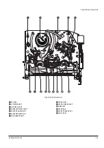
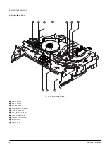
4. Disassembly and Reassembly
4-1 Cabinet and PCB
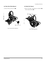
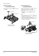
4-1-1 Cabinet Top Removal
Œ
REMOVE 3 SCREWS
´
Lift up the Cabinet Top in the direction of arrow.
Fig. 4-1 Cabinet Top Removal
4-1-2 Ass’y Bottom Cover Removal
Œ
RELEASE 2 HOOKS
(Bottom View)
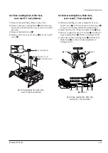
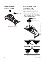
4-1-4 Function PCB Removal
Œ
RELEASE 1 HOOK
Fig. 4-4 Function PCB Removal
Fig. 4-2 Ass’y Bottom Cover Removal
´
RELEASE 3 HOOKS
(Bottom View)
Œ
RELEASE 3 HOOKS
(Top View)
Fig.4-3 Ass’y Front Panel Removal
4-1-3 Ass’y Front Panel Removal
Summary of Contents for DVD-V5450
Page 23: ...Reference Information 14 12 Samsung Electronics Fig 14 14 Mecha Timing Chart Kaiser II ...
Page 37: ...Reference Information 14 26 Samsung Electronics MEMO ...
Page 49: ...Product Specification 2 12 Samsung Electronics MEMO ...
Page 109: ...Operating Instructions 12 60 Samsung Electronics MEMO ...
Page 237: ...Troubleshooting 5 34 Samsung Electronics MEMO ...
Page 247: ...Exploded View and Parts List 6 10 Samsung Electronics MEMO ...
Page 263: ...Block Diagram 8 2 MEMO Samsung Electronics ...
Page 265: ...PCB Diagrams 10 2 Samsung Electronics 10 1 VCR Main PCB COMPONENT SIDE ...
Page 266: ...PCB Diagrams 10 3 Samsung Electronics CONDUCTOR SIDE ...
Page 267: ...PCB Diagrams 10 4 Samsung Electronics 10 2 DVD Main PCB COMPONENT SIDE ...
Page 268: ...PCB Diagrams 10 5 Samsung Electronics CONDUCTOR SIDE ...
Page 270: ...9 1 9 Wiring Diagram Samsung Electronics ...
Page 271: ...Wiring Diagram 9 2 MEMO Samsung Electronics ...


