CHANGING
SETUP MENU
4.
4.
Use the UP/DOWN or LEFT/RIGHT button to
select the desired item. Then press the ENTER
button.
5.
5.
Use the UP/DOWN button to select OPTION.
Then press the ENTER button.
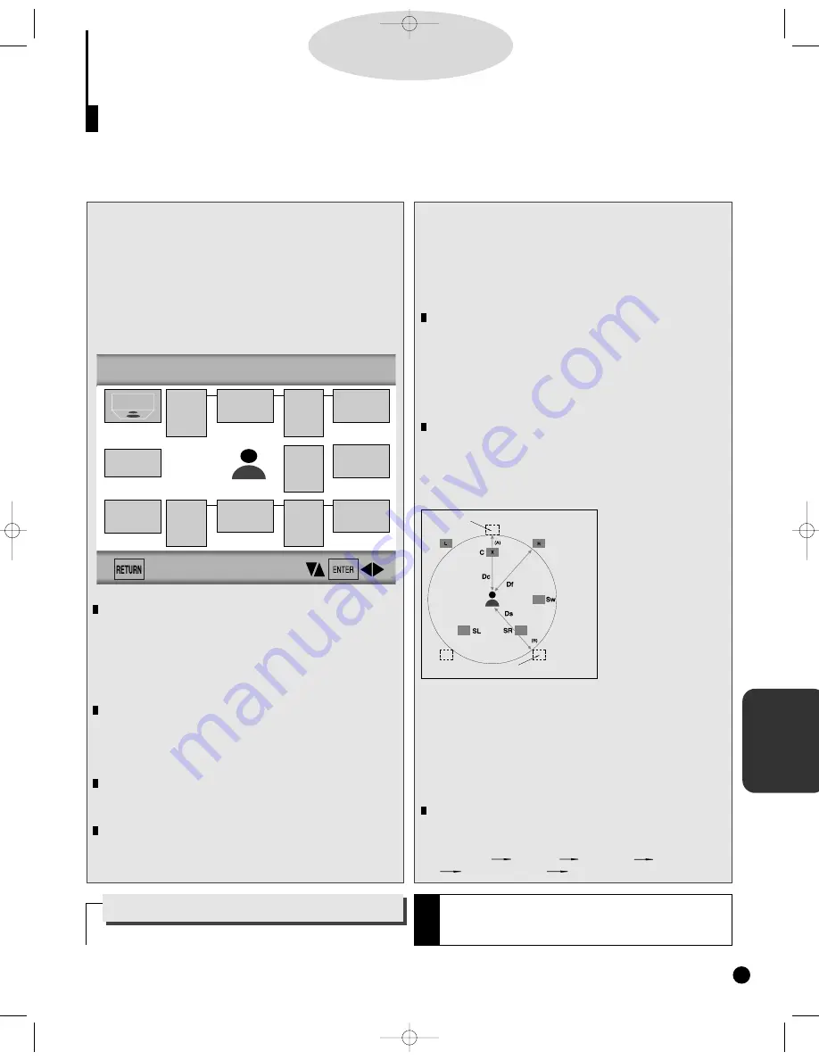
Setting up SPEAKER MODE
• If you have connected the system to a speaker with low fre-
quencies of 100Hz or below, select 'Found(Large)'.
• If you have connected the system to a speaker without low
frequencies of 100Hz or below, select 'Found(Small)'. But if
you don't connect to a subwoofer, always select
'Found(Large)' for Front Speakers(L/R).
• When you don't connect to speaker, select 'Not found'.
Setting up DELAY TIME
• When 5.1CH Surround Sound is played, you can enjoy the
best sound if the distance between you and each speaker is
the same. You can set Delay Time in the Center/Surround
Speaker to customize the sound to the acoustic of your
room.
• Setting CENTER
SPEAKER
If the distance of Dc is
equal to or longer than
the distance of Df in the
left figure, set the mode
as Oms. Otherwise,
change the setting
according to the table
below.
(A) = Df - Dc
Distance of (A)(cm) Setting(ms)
50 1.3
100 2.6
150 3.9
200 5.3
• Setting SURROUND SPEAKERS
If the distance of Df is equal to the distance of Ds in the
above, set the mode as Oms. Otherwise, change the setting
according to the table below.
(B) = Df - Ds
Distance of (B)(cm) Setting(ms)
200 5.3
400 10.6
600 15.9
Setting up TEST
The test output signals come clockwise starting from the Front
Speaker(L). Adjust Channel Balance to match to the volume of
test signals memorized in the system.
FRONT(L) CENTER FRONT(R) SUBWOOFER
SURROUND(R) SURROUND(L)
S
urround Sound Speaker Setup (DVD-909 only)
D
D
D
D
V
V
V
V
D
D
D
D
37
1.
1.
Press the SETUP button in play or stop mode.
2.
2.
Press the UP/DOWN button to select AUDIO
OPTIONS. Then press the ENTER button.
3.
3.
Use the UP/DOWN button to select SPEAKER
SETUP. Then press the ENTER button.
SPEAKER MODE
You can set a mode in the system that's currently used.
Initially it is set as follows:
• Front speaker (L/R) : Found (Large)
• Center speaker : Not found
• Subwoofer : Not found
• Surround speaker (L/R) : Not found
DELAY TIME
You can customize the sound to conform to the acoustics of
your room by adding a delay effect to the sound of the Center
Speaker and Surround Speaker. Initially it is set as "Oms (mil-
liseconds)".
TEST
It sends test signals memorized in the system to each speaker
except Subwoofer.
CHANNEL BALANCE
Adjust the output level of a speaker by using test signals that
are memorized in the system. Initially it is set as "OdB".
Speaker Mode
(Front L)
Speaker Mode
(Center)
Speaker Mode
(Front R)
Speaker Mode
(Subwoofer)
Speaker Mode
(Surround R)
Delay Time
(Surround L/R)
Oms
Speaker Mode
(Surround L)
TEST
Channel
Balance
(Center)
OdB
Channel
Balance
(Subwoofer)
OdB
Channel
Balance
(Surround L)
OdB
Delay Time
(Center)
Oms
Channel
Balance
(Surround R)
OdB
• Arrange all
speakers
within circle.
Ideal CENTER SPEAKER position
Ideal SURROUND SPEAKER position
SPEAKER SETUP
How to make the SETUP MENU disappear or
return to menu screen during set up.
Press RETURN button.
The DVD-909 has a Speaker Setup feature that allows you to customize your surround sound setup.
Only when the DVD disc is played or the disc isn’t loaded, this feature will be activated.
N
O
T
E
• The subwoofer test output signal is lower than the other
speakers.
• The MPEG Multichannel logo is a trademark registered by
PHILIPS Corporation.
DVD-YURO909/709 11/4/95 10:01 AM Page 37
Summary of Contents for DVD-709
Page 23: ...Reference Information 2 16 Samsung Electronics MEMO ...
Page 57: ...5 18 Samsung Electronics Disassembly Reaasembly MEMO ...
Page 97: ...Exploded Views and Parts List 8 8 Samsung Electronics MEMO ...
Page 109: ...9 12 Samsung Electronics Electrical Parts List MEMO ...
Page 115: ...PCB Diagrams 11 2 Samsung Electronics 11 1 Main COMPONENT SIDE SOLDER SIDE ...
Page 116: ...PCB Diagrams Samsung Electronics 11 3 11 2 Jack ...
Page 119: ...Wiring Diagram 12 2 Samsung Electronics MEMO ...
Page 121: ...Schematic Diagrams 13 2 Samsung Electronics 13 1 S M P S ...
Page 122: ...Schematic Diagrams Samsung Electronics 13 3 13 2 Main Power Supply ...
Page 123: ...Schematic Diagrams 13 4 Samsung Electronics 13 3 Main Micom ...
Page 124: ...Schematic Diagrams Samsung Electronics 13 5 13 4 Servo ...
Page 126: ...Schematic Diagrams Samsung Electronics 13 7 DVD 909 OPTION 13 6 Audio ...
Page 127: ...Schematic Diagrams 13 8 Samsung Electronics 13 7 5 1 Channel Audio DVD 909 Only ...
Page 128: ...Schematic Diagrams Samsung Electronics 13 9 13 8 RF ...
Page 129: ...Schematic Diagrams 13 10 Samsung Electronics 13 9 ZiVA ...
Page 130: ...Schematic Diagrams Samsung Electronics 13 11 13 10 DSP ...
Page 132: ...Schematic Diagrams Samsung Electronics 13 13 13 12 Component DVD 909 Only Option ...
Page 134: ...Schematic Diagrams Samsung Electronics 13 15 13 14 Mute ...
Page 136: ...Schematic Diagrams Samsung Electronics 13 17 13 17 Deck ...
Page 137: ...Schematic Diagrams 13 18 Samsung Electronics 13 18 Remote Control ...
Page 140: ...4 TABLE OF CONTENTS DVD YURO909 709 11 4 95 9 59 AM Page 4 ...


