5
Flexible hoses
The flow and return connections of the back of the heat pump are 1” BSP
male and we would recommend connecting the water pipework with the flexi
hoses. This is to help reduce and vibration from the unit travelling back into
the house and also allows for ease of maintenance.
All external pipework Must be installed to meet MCS guidelines
Mounting Feet
The unit needs to be mounted 100mm above ground, the best way to do this
is to use the flexi foot pair supplied in our kit, these come with the mounting
bolts as standard.
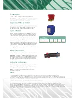
Expansion vessel, pressure gauge,
pressure relief valve & filling loop
In pressurised heating systems, most heating engineers decide to use a
Robokit. This combines all of these components into one handy box. The
expansion vessel would be sized exactly as it would for a boiler.
If the system requires the need to be run as an open vented system then the
components listed above will not be needed, Samsung units can run anywhere
between 0-3 bar pressure.
Pump
The circulation pump on the Samsung system will need to provide a minimum
flow rate in order for the unit to perform correctly.
The units need to have the following flow rates;
• 5 kW - 12 L/min
• 9 kW - 20 L/min
• 16 kW - 30 L/min
The static resistance through the units are;
• 5 kW - 10 kPa
• 9 kW - 10 kPa
• 16kW - 15 kPa
• Flow meter - 5 kPa
• Cylinders ~ 5 kPa
The best way to overcome the pressure and to achieve the minimum flow
rates would be to use one circulation pump size accordingly to the system.
Flow switch and flow meter
Heat pumps have to have a continuous flow rate at all times during operation,
to check and measure that the flow rate is correct the flow switch that is
supplied with the control kit needs to be positioned on the primary return to
the heat pump. If for any reason the flow of the system does not engage the
paddle within the flow switch an E911 error will appear.
E911
The E911 fault will appear if the flow rate of the system is below 16 L/m for the 9 kW upwards and 6 L/m for the 5 kW. To avoid this fault, a hydraulic
separator can be used to split the system.
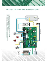
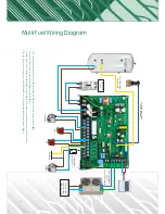
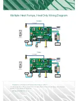
The flow switch is included within the control kit, this has to be installed with at least 150mm of straight pipe on either side and can be positioned horizontally
or vertically. The connections are 1” BSP female and the wire is 2 metres long and will need to connect into the MIM board. The wire can be extended if
needed using the same quality of cable.
The flow switch can be installed with the flow meter, it is recommended that it is installed into the flow side of the flow meter. Adapters will be needed to do
so and will come as part of the Solfex kit. The flow switch will need to be installed indoors as it is not outdoor (IP65) rated.


