24
What comes with the unit?
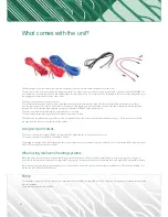
The first thing that you will see when you open the box (unless you open it upside down) should be the sensor cables.
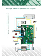
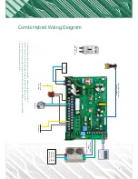
The blue sensor cable is used to measure the temperature inside the cylinder and connects into a yellow socket on the control board labelled CNS042. The
sensor should be located in the top half of the cylinder above the immersion heater. The sensor must also be situated so that it cannot be easily pulled out of
the tapping and so that it is not near any mains cables.
The other cables you will see are two red ones.
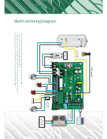
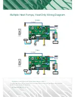
The red cable with the black plug is only used on multiple unit systems with a master and a slave. This sensor measures the temperature to avoid any
excessive temperatures. This cable is connected to the master unit and should be positioned so that it measures the flow temperature into the hydraulic
separator. The socket that this cable plugs into is black and is labelled as CNS047 on the control board.
The other red cable with the blue plug can be discarded as it is not used.
The black cable with the red plug can also be discarded as this is also not used.
The other three red white and brown cables are used in systems with a backup heater or master slave systems see page 11. These are used to send the
run signal from the master over to the slave when needed.
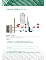
Using two port valves
The two port valve for the cylinder (DHW), B17 is Brown, B15 is Blue and the rest are not needed or used.
The two port valve for heating is B18 Live and B15 Neutral.
The heating is controlled with a field supplied stat, time clock or from an underfloor wiring centre or manifold. On the control board, B20 is permanently live
(240V AC), the signal is returned back to B22.
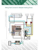
When using multi zone heating systems
When the call for heat is made from a stat it will in turn operate the zone valve, in the zone valves a switch links to orange to the grey wire, the grey is
connected to B20 (permanent live) and the orange to B22 (run signal). This sequence will open the valves and send a run signal to the heat pump to start up.
After each run of the unit, the pump will continue to run for a minute to continue to circulate the heat out of the outdoor unit. The hot water heating is not
affected and the DHW will still take priority.
Pump
The circulation pump will need to be wired to the control board and should be as follows; B8 is Live, B7 is Neutral. If two pumps are required then wire both
the same terminals.
The maximum power for this is 500W.

