3
.
Installing the Product
Confidential
112
English 8/2019. Rev 0.0
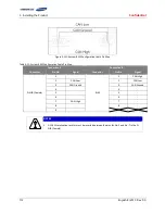
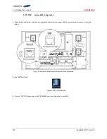
Figure 3-131: System BMS Configuration Cable Pin Map
Table 3-12: System BMS Configuration Cable Pin Map
Connection A
Connection B
Connector
Pin No.
Signal
Connector
Pin No.
Signal
D-SUB (Female)
1
-
RJ45
1
CAN High
2
CAN Low
2
CAN Low
3
CAN Ground
3
CAN Ground
4
-
4
-
5
-
5
-
6
-
6
-
7
CAN High
7
-
8
-
8
-
9
-
NOTICE
A 120
termination resistor must be inserted between the pins for No. 2 and No. 7 in the D-
SUB (Female).
Summary of Contents for 136S
Page 1: ...Confidential English 8 2019 Rev 0 0 LIB System for UPS Installation Manual 136S ...
Page 4: ...Confidential English 8 2019 Rev 0 0 ...
Page 10: ...Important Safety Instructions Confidential vi English 8 2019 Rev 0 0 ...
Page 18: ...Confidential Table of Contents viii English 8 2019 Rev 0 0 ...
Page 153: ...Confidential Memo ...
Page 154: ...Confidential Memo ...
Page 155: ...Confidential Memo ...
Page 156: ...www SamsungSDI com ...


