Confidential
vi
English 8/2019. Rev 0.0
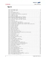
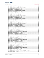
Figure 3-91: Module #1 to Module #2 Signal Cabling
Figure 3-92: Module #2 to Module #3 Signal Cabling
Figure 3-93: Module #3 to Module #4 Signal Cabling
Figure 3-94: Module #4 to Module #5 Signal Cabling
Figure 3-95: Module #5 to Module #6 Signal Cabling
Figure 3-96: Module #6 to Module #7 Signal Cabling
Figure 3-97: Module #7 to Module #8 Signal Cabling
Figure 3-98: Module #8 to Module #9 Signal Cabling
Figure 3-99: Module #9 to Module #10 Signal Cabling
Figure 3-100: Module #10 to Module #11 Signal Cabling
Figure 3-101: Module #11 to Module #12 Signal Cabling
Figure 3-102: Module #12 to Module #13 Signal Cabling
Figure 3-103: Module #13 to Module #14 Signal Cabling
Figure 3-104: Module #14 to Module #15 Signal Cabling
Figure 3-105: Module #15 to Module #16 Signal Cabling
Figure 3-106: Module #16 to Module #17 Signal Cabling
Figure 3-107: Pre-Punched Hole for Signal Cable
Figure 3-108: Signal Cabling Examples of Left Alignment of SMU
...................................................................................... 95
Figure 3-109: Termination Resistor Setting for Last SMU
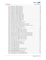
Figure 3-110: DC Power Cables from SMPS Assembly 3 Phase Type A to SMU
................................................................. 97
Figure 3-111: DC Power Cables from SMPS Assembly 3 Phase Type B to SMU
................................................................. 97
Figure 3-112: CAN Signal Cable Connection from SMPS Assembly 3 Phase Type A to SMU
............................................ 98
Figure 3-113: TCP/IP Cable Connection to SMPS Assembly
................................................................................................ 98
Figure 3-114: Dry Contact Cable Connection to SMPS Assembly
....................................................................................... 99
Figure 3-115: MCCB Extra Auxiliary Connection
Figure 3-116: AC Input Terminals of SMPS Assembly 3 Phase Type A
............................................................................ 100
Figure 3-117: AC Input Terminals of SMPS Assembly 3 Phase Type B
............................................................................. 100
Figure 3-118: AC Input Terminals of SMPS Assembly 1 Phase Type A
............................................................................ 101
Figure 3-119: AC Input Terminals of SMPS Assembly 1 Phase Type B
............................................................................. 101
Figure 3-120: SMPS Assembly 3 Phase Type A - AC Input Terminals with Cables Attached
.......................................... 102
Figure 3-121: SMPS Assembly 3 Phase Type B - AC Input Terminals with Cables Attached
.......................................... 102
Figure 3-122: SMPS Assembly 1 Phase Type A - AC Input Terminals with Cables Attached
.......................................... 103
Figure 3-123: SMPS Assembly 1 Phase Type B - AC Input Terminals with Cables Attached
.......................................... 103
Figure 3-124: AC Input Terminals of SMPS Assembly 3 Phase Type A
............................................................................ 103
Figure 3-125: AC Input Terminals of SMPS Assembly 3 Phase Type B
............................................................................. 104
Figure 3-126: AC Input Terminals of SMPS Assembly 1 Phase Type A
............................................................................ 104
Figure 3-127: AC Input Terminals of SMPS Assembly 1 Phase Type B
............................................................................. 105
Figure 3-128: Grounding Points (2 EA)
Figure 3-129: Connecting the DC Link High Current Terminals
........................................................................................ 107
Figure 3-130: Rack BMS Configuration Cable Pin Map
Figure 3-131: System BMS Configuration Cable Pin Map
Figure 3-132: System BMS Communication Cable Pin Map
............................................................................................. 113
Figure 3-133: BATTMON Splash Window
Figure 3-134: Installer Access Password
Figure 3-135: BATTMON Splash Window
Figure 3-136: Warning Pop-up Window
Figure 3-137: Selecting System BMS Configuration Parameter File
................................................................................ 116
Figure 3-138: BATTMON Splash Window : Warning Pop-up Window
............................................................................. 117
Figure 3-139: Warning Pop-up Window
Figure 3-140: Selecting Rack BMS Configuration Parameter File
.................................................................................... 117
Figure 3-141: Cable Connections for Rack BMS Configuration
........................................................................................ 118
Figure 3-142: Rack BMS CAN ID Numbers for a Multiple Rack System
........................................................................... 118
Figure 3-143: Rack BMS termination switch and CAN cable connection
........................................................................ 119
Summary of Contents for 136S
Page 1: ...Confidential English 8 2019 Rev 0 0 LIB System for UPS Installation Manual 136S ...
Page 4: ...Confidential English 8 2019 Rev 0 0 ...
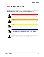
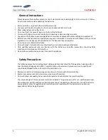
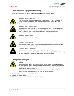
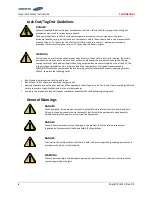
Page 10: ...Important Safety Instructions Confidential vi English 8 2019 Rev 0 0 ...
Page 18: ...Confidential Table of Contents viii English 8 2019 Rev 0 0 ...
Page 153: ...Confidential Memo ...
Page 154: ...Confidential Memo ...
Page 155: ...Confidential Memo ...
Page 156: ...www SamsungSDI com ...


