


EB 8384-1 EN
43
Connections
Selecting cables and wires
Observe
clause 12 of
EN 60079-14: 2008
(VDE 0165, Part 1) for installation of the in-
trinsically safe circuits.
Clause 12.2.2.7 applies when running multi-
core cables and wires with more than one
intrinsically safe circuit.
The radial thickness of the insulation of a
conductor for common insulating materials
(e.g. polyethylene) must not be smaller than
0.2 mm. The diameter of an individual wire
in a fine-stranded conductor must not be
smaller than 0.1 mm. Protect the conductor
ends against splicing, e.g. by using wire-end
ferrules. When two separate cables or wires
are used for connection, an additional cable
gland can be installed. Seal cable entries left
unused with plugs. Fit equipment used in
ambient temperatures
below –20 °C
with
metal cable entries.
Equipment for use in zone 2/zone 22
In equipment operated according to type of
protection Ex nA II (non-sparking equipment)
according to EN 60079-15: 2003, circuits
may be connected, interrupted, or switched
while energized only during installation,
maintenance, or repair.
Equipment connected to energy-limited cir-
cuits with type of protection Ex nL (energy-
limited equipment) according to EN 60079-
15: 2003 may be switched under normal
operating conditions.
The maximum permissible values specified
in the statement of conformity and its ad
-
denda apply when interconnecting the
equipment with energy-limited circuits in
type of protection Ex nL IIC.
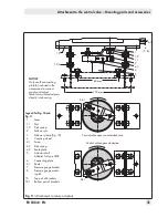
Cable entry
Cable entry with M20 x 1.5 cable gland, 6
to 12 mm clamping range.
There is a second M20 x 1.5 threaded hole
in the housing that can be used for addition-
al connection, when required.
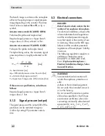
The screw terminals are designed for wire
cross-sections of 0.2 to 2.5 mm². Tighten the
screws by 0.5 to 0.6 Nm.
The wires for the set point must be connected
to the terminals 11 and 12 located in the
housing. Only use a
current source
!
NOTICE
An incorrect electric signal will dam
-
age the positioner.
Do not connect the positioner to a
voltage source. The incorrect connec-
tion of a voltage source of just
around 7 V (or around 2 V when
connected to the wrong pole) by mis-
take can damage the positioner.
Do not interrupt the minimum current
3.7 mA for longer than two minutes.
In general, it is not necessary to connect the
positioner to a bonding conductor. Should
this be required, however, this conductor can
be connected inside the device.
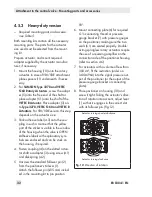
For operation of the limit contacts in
Type 3730-11/-13/-18 Positioners, switching
amplifiers which comply with EN 60947-5-6
must be connected to terminals 41/42 and
51/52 in the output circuit.
Observe the relevant regulations for installa-
tion in hazardous areas.
Refer to Fig. 15 for the terminal assignment.
Summary of Contents for TROVIS 3730-1
Page 64: ...64 EB 8384 1 EN...
Page 65: ...EB 8384 1 EN 65...
Page 66: ...66 EB 8384 1 EN...
Page 67: ...EB 8384 1 EN 67...
Page 68: ...68 EB 8384 1 EN...
Page 69: ...EB 8384 1 EN 69...
Page 70: ...70 EB 8384 1 EN...
Page 71: ...EB 8384 1 EN 71...
Page 72: ...72 EB 8384 1 EN...
Page 73: ...EB 8384 1 EN 73...
Page 74: ...74 EB 8384 1 EN...
Page 75: ...EB 8384 1 EN 75...


