


16
EB 8384-1 EN
Attachment to the control valve – Mounting parts and accessories
4.1
Direct attachment
4.1.1
Type 3277-5 Actuator
−
Required mounting parts and accesso-
ries: Table 1
−
Observe the travel table on page 15.
Actuator with 120 cm²
(see Fig. 3)
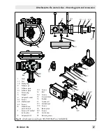
Depending on the type of positioner attach-
ment, the signal pressure is routed either left
or right of the yoke through a hole to the ac-
tuator diaphragm. Depending on the fail-
safe action of the actuator "actuator stem
extends" or "actuator stem retracts" (valve
closes or opens upon supply air failure), the
switchover plate (9) must first be attached to
the actuator yoke. Align the switchover plate
with the corresponding symbol for left or
right attachment according to the marking
(view looking onto the switchover plate).
1.
Mount connecting plate (6) or pressure
gauge bracket (7) with pressure gauges
on the positioner, making sure the two
seals (6.1) are seated properly.
2.
Remove screw plug (4) on the back of the
positioner and seal the signal pressure
output (38) on the connecting plate (6) or
on the pressure gauge bracket (7) with
the stopper (5) included in the accesso-
ries.
3.
Place follower clamp (3) on the actuator
stem, align it and screw tight so that the
mounting screw is located in the groove
of the actuator stem.
4.
Mount cover plate (10) with narrow side
of the cut-out (Fig. 3, on the left) pointing
towards the signal pressure connection.
Make sure that the gasket (14) points to-
wards the actuator yoke.
5.
15 mm travel:
Keep the follower pin (2)
on the
M
lever (1) on the back of the po-
sitioner in the pin position
35
(delivered
state).
7.5 mm travel:
Remove the follower pin
(2) from the pin position
35
, reposition it
in the hole for pin position
25
and screw
tight.
6.
Insert formed seal (15) into the groove of
the positioner housing and insert the seal
(10.1) on the back of the housing.
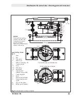
7. Place positioner on the cover plate (10)
in such a manner that the follower pin (2)
rests on the top of the follower clamp (3).
Adjust the lever (1) correspondingly and
open the positioner cover to hold the po
-
sitioner shaft in position at the cap or
switch (Fig. 16). The lever (1) must rest on
the follower clamp with spring force.
Mount the positioner on the cover plate
(10) using the two fixing screws.
Note applying to all types of at-
tachment except for direct attach-
ment to Type 3277-5:
The signal pressure output at the
back must be sealed by the screw
plug (4, order no. 0180-1254) and
the associated O-ring (order no.
0520-0412).
8.
Mount cover (11) on the other side. Make
sure that the vent plug is located at the
bottom when the control valve is installed
to allow any condensed water that col
-
lects to drain off.
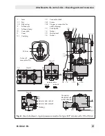
9 11
Supply 9
Output 38
5
6
4
7
6
10
10.1
3
2
1
15
6.1
1.1
1.2
14
8
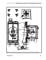
Fig. 3:
Direct attachment – Signal pressure connection for Type 3277-5 Actuator with 120 cm²
Summary of Contents for TROVIS 3730-1
Page 64: ...64 EB 8384 1 EN...
Page 65: ...EB 8384 1 EN 65...
Page 66: ...66 EB 8384 1 EN...
Page 67: ...EB 8384 1 EN 67...
Page 68: ...68 EB 8384 1 EN...
Page 69: ...EB 8384 1 EN 69...
Page 70: ...70 EB 8384 1 EN...
Page 71: ...EB 8384 1 EN 71...
Page 72: ...72 EB 8384 1 EN...
Page 73: ...EB 8384 1 EN 73...
Page 74: ...74 EB 8384 1 EN...
Page 75: ...EB 8384 1 EN 75...


