


8
EB 8384-1 EN
Design and principle of operation
3
Design and principle of oper
-
ation
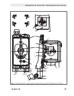
The electropneumatic positioner is mounted
on pneumatic control valves and is used to
assign the valve position (controlled variable
x) to the control signal (set point w). The po-
sitioner compares the electric control signal
of a control system to the travel or opening
angle of the control valve and issues a signal
pressure (output variable y) for the pneumat-
ic actuator.
The positioner is designed depending on
which accessories are selected either for di-
rect attachment to SAMSON Type 3277 Ac-
tuators or for attachment to actuators ac-
cording to NAMUR (IEC 60534-6).
Additionally, a coupling wheel included in
the accessories is required to transfer the ro-
tary motion for rotary actuators according to
VDI/VDE 3845.
Springless rotary actuators require a revers-
ing amplifier included in the accessories to
permit the powered operation in either di
-
rection.
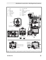
The positioner consists of a travel sensor sys-
tem proportional to resistance, an analog
i/p converter with a downstream air capaci
-
ty booster and the electronics with microcon-
troller. The positioner is fitted with two ad-
justable software limit contacts as standard
to indicate the valve's end positions.
The position of the valve stem is transmitted
as a either an angle of rotation or travel
over the pick-up lever to the travel sensor (2)
and supplied to an analog PD controller (3).
An A/D converter (4) transmits the position
of the valve to the microcontroller (5).
The PD controller (3) compares this actual
position to the 4 to 20 mA DC control signal
after it has been converted by the A/D con-
verter (4).
In case of a system deviation, the activation
of the i/p module (6) is changed so that the
actuator of the control valve (1) is pressur-
ized or vented accordingly over the down-
stream booster (7). This causes the valve
plug to move to the position determined by
the set point.
The supply air is supplied to the booster and
the pressure regulator (8). An intermediate
flow regulator (9) with fixed settings is used
to purge the positioner and, at the same
time, guarantees trouble-free operation of
the booster.
The output signal pressure supplied by the
booster can be limited to 2.4 bar by activat-
ing the P9 parameter.
The volume restriction (10) is used to opti-
mize the positioner by adapting it to the ac-
tuator size.
Tight-closing function:
The pneumatic actuator is completely filled
with air or vented as soon as the set point
falls below 1 % or exceeds 99 % (see end
position function in P10 and P11 parame-
ters).
Summary of Contents for TROVIS 3730-1
Page 64: ...64 EB 8384 1 EN...
Page 65: ...EB 8384 1 EN 65...
Page 66: ...66 EB 8384 1 EN...
Page 67: ...EB 8384 1 EN 67...
Page 68: ...68 EB 8384 1 EN...
Page 69: ...EB 8384 1 EN 69...
Page 70: ...70 EB 8384 1 EN...
Page 71: ...EB 8384 1 EN 71...
Page 72: ...72 EB 8384 1 EN...
Page 73: ...EB 8384 1 EN 73...
Page 74: ...74 EB 8384 1 EN...
Page 75: ...EB 8384 1 EN 75...


