


30
EB 8384-1 EN
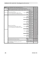
Attachment to the control valve – Mounting parts and accessories
4.5
Attachment to rotary actu
-
ators
−
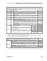
Required mounting parts and accesso-
ries: Table 5
−
Observe the travel table on page 15.
The positioner is mounted to the rotary actu
-
ator using two pairs of brackets.
Prior to attaching the positioner to the
SAMSON Type 3278 Rotary Actuator,
mount the associated adapter (5) to the free
end of the rotary actuator shaft.
Note:
On attaching the positioner as de-
scribed below, it is imperative that
the actuator's direction of rotation is
observed.
1.
Place follower clamp (3) on the slotted
actuator shaft or adapter (5).
2.
Place coupling wheel (4) with flat side
facing the actuator on the follower clamp
(3). See Fig. 11 to align slot so that it
matches the direction of rotation when
the valve is in its closed position.
3.
Fasten the coupling wheel (4) and follow-
er clamp (3) tightly onto the actuator
shaft using screw (4.1) and disk spring
(4.2).
4.
Fasten the bottom pair of brackets (10.1)
with the bends pointing either facing to
the inside or to the outside (depending
on the actuator size) onto the actuator
housing. Position the top pair of brackets
(10) and fasten.
5. Mount connecting plate (6) or pressure
gauge bracket (7) with pressure gauges
on the positioner, making sure the two
seals are seated properly.
Double-acting
springless rotary actuators require the
use of a reversing amplifier on the con-
nection side of the positioner housing
(see section 4.6).
6.
Unscrew the standard follower pin (2)
from the positioner's
M
lever (1). Use the
metal follower pin (Ø 5 mm) included in
the mounting kit and screw tight into the
hole for pin position
90°
.
7. Place positioner on the top bracket (10)
and fasten tight. Taking the actuator's di-
rection of rotation into account, adjust le-
ver (1) so that it engages in the slot of the
coupling wheel (4) with its follower pin
(Fig. 11). It must be guaranteed that the
lever (1) is parallel to the long side of the
positioner when the actuator is at half its
angle of rotation.
8.
Stick the scale plate (4.3) on the coupling
wheel so that the arrow tip indicates the
closed position and it can be easily read
when the valve is installed.
1.2
1.1
1
2
4.1
4.2
5
3
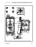
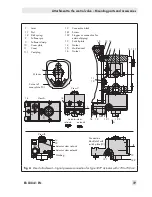
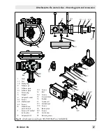
Fig. 10:
Mounting the coupling wheel on
Type 3278
10
10.1
6
(7, 8)
1.1
2
4.3
5
6.1
4
1.2
1
130 mm
80 mm
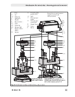
NOTICE
Only use the connecting
plate (6) included in the
accessories to connect
supply and output.
Never screw threaded parts
directly into housing.
Legend for Fig. 10 and
Fig. 11
1
Lever
1.1
Nut
1.2
Disk spring
2
Follower pin
3
Follower clamp (Fig. 10)
4
Coupling wheel
4.1
Screw
4.2
Disk spring
4.3
Scale plate
5
Actuator shaft
Adapter for Type 3278
6
Connecting plate
6.1
Seals
7
Pressure gauge bracket
8
Pressure gauge mount-
ing kit
10
Top pair of brackets
10.1
Bottom pair of brackets
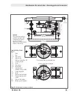
Control valve opens counterclockwise
Control valve opens clockwise
Slot
Slot
Fig. 11:
Attachment to rotary actuators
Summary of Contents for TROVIS 3730-1
Page 64: ...64 EB 8384 1 EN...
Page 65: ...EB 8384 1 EN 65...
Page 66: ...66 EB 8384 1 EN...
Page 67: ...EB 8384 1 EN 67...
Page 68: ...68 EB 8384 1 EN...
Page 69: ...EB 8384 1 EN 69...
Page 70: ...70 EB 8384 1 EN...
Page 71: ...EB 8384 1 EN 71...
Page 72: ...72 EB 8384 1 EN...
Page 73: ...EB 8384 1 EN 73...
Page 74: ...74 EB 8384 1 EN...
Page 75: ...EB 8384 1 EN 75...