


28
EB 8384-1 EN
Attachment to the control valve – Mounting parts and accessories
4.4
Attachment to Type 3510
Micro-flow Valve
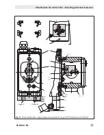
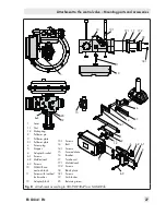
Fig. 9
−
Required mounting parts and accesso-
ries: Table 3
−
Observe the travel table on page 15.
The positioner is attached to the valve yoke
using a bracket.
1.
Fasten the bracket (9.1) to the stem con-
nector.
2.
Screw the two pins (9.2) to the bracket
(9.1) of the stem connector (9), place the
follower plate (3) on top and use the
screws (9.3) for fastening.
3.
Mount the travel indication scale (acces-
sories) to the outer side of the yoke using
the hex screws (12.1), ensuring that the
scale is aligned with the stem connector.
4.
Fasten the hex bar (11) onto the outer
side of yoke by screwing the M8 screws
(11.1) directly into the holes on the yoke.
5. Fasten the bracket (10) to the hex bar
(11) using the hex screw (10.1), washer
and tooth lock washer.
6.
Mount connecting plate (6) or pressure
gauge bracket (7) with pressure gauges
on the positioner, making sure the two
seals are seated properly.
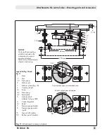
7. Unscrew the standard M lever (1) includ-
ing follower pin (2) from the positioner
shaft.
8.
Take the S lever (1) and screw the follow-
er pin (2) in the hole for pin position 17.
9. Place the S lever on the positioner shaft
and screw tight using the disk spring (1.2)
and nut (1.1).
Move lever once all the way as far as it
will go in both directions.
10.
Place positioner on the bracket (10) in
such a manner that the follower pin
slides into the groove of the follower pin
(3). Adjust the lever (1) correspondingly.
Screw the positioner to the bracket (10)
using both its screws.
S lever
NOTICE
Only use the connecting plate (6) in-
cluded in the accessories to connect
SUPPLY and OUTPUT.
Never screw threaded parts directly
into housing.
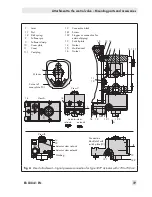
1
Lever
1.1 Nut
1.2
Disk spring
2
Follower pin
3
Follower plate
6
Connecting plate
6.1
Seals
7
Pressure gauge bracket
8
Pressure gauge
mounting kit
9
Stem connector
9.1 Bracket
9.2 Pin
9.3 Screws
10
Bracket
10.1
Screw
11
Hexagon bolt
11.1
Screws
12.1
Screws
10.1
1
2
1.1
1.2
6.1
6
7
8
10
9
9.1
11
11.1
3
12.1
9.2
9.3
Fig. 9:
Attachment to Type 3510 Micro-flow Valve
Summary of Contents for TROVIS 3730-1
Page 64: ...64 EB 8384 1 EN...
Page 65: ...EB 8384 1 EN 65...
Page 66: ...66 EB 8384 1 EN...
Page 67: ...EB 8384 1 EN 67...
Page 68: ...68 EB 8384 1 EN...
Page 69: ...EB 8384 1 EN 69...
Page 70: ...70 EB 8384 1 EN...
Page 71: ...EB 8384 1 EN 71...
Page 72: ...72 EB 8384 1 EN...
Page 73: ...EB 8384 1 EN 73...
Page 74: ...74 EB 8384 1 EN...
Page 75: ...EB 8384 1 EN 75...


