background image

12

5.  INSTALLATION

Install  the  pump  in  a  frost-free/dust-free  and  well-

ventilated  location  that  is  protected  from  adverse

weather conditions.

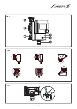
5.1 Mounting (See FIG. 1)

Risk of damage to the pump ! Dirt can

cause the pump to malfunction.

Do  not  install  until  all  welding  and  soldering  work  has

been  completed  and  the  pipe  system  has  been

flushed (if required).

For  connection  with  the  water  supply

network,  the  use  of  new  accessories  is

necessary.

- Mount the pump in an easily accessible location with

gate  valves  at  both  suction  and  discharge  sides  in

order  to  facilitate  subsequent  inspections  or

replacements.

- It  may  be  necessary,  depending  on  the  application

to  replace  the  spring  discharge-side  gate  valve  with

a spring-activated non-return valve.

- The  gate  valves  are  not  required  on  Thermo’clock  as

their  functions  are  assumed  by  the  integrated  non-

return and ball valves.

- Install the pump without voltage with the pump shaft in

a horizontal position.

- Observe the installation positions (

FIG. 2

).

Risk of damage to the pump !

The 

screwed 

cable 

gland 

(FIG.  1  -  item  3)  must  point  downwards  to  prevent

water  easily  penetrating  the  motor  housing.  If

necessary, rotate the motor housing after releasing the

union nut (FIG. 1 - item 4). Do not damage the housing

gasket.

- The directional arrow on the pump housing shows the

direction of flow.

- On  the  Thermo'clock  the  non-return  valve 

(

FIG.  1  -  item  1

)  is  screwed  into  the  dishcarge  port,

whilst  the  ball  shut-off  valve  (

FIG.  1  -  item  2

)  is

screwed into the suction port.

- The ball valve is open when the slot is in line with the

direction of flow.

- The ball valve is closed when the slot is perpendicular

to the direction of flow.

Risk of damage to the pump !

In  the  case  of  the  versions  with  check

valve  and  non-return  valve,  these  are  already  pre-

assembled  with  a  tightening  torque  of  15  Nm  (hand-

tight).  If  the  tightening  torque  is  too  high,  this  will

destroy the valve screw connection and the O-ring.

When  installing  the  valve,  use  a  wrench  to  prevent  it

from turning!

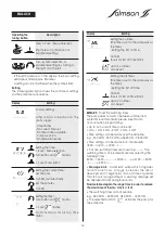
signifies  that  the  Thermo’clock  maintains  the  warm

water  temperature  in  the  return  of  the  drinking  water

circulation  system  using  the  integrated  temperature

sensor.

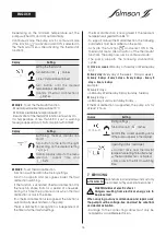
Thermal disinfection

In  addition,  the  Thermo’clock  offers  a  routine  for  the

recognition  and  support  of  boiler  thermal  disinfection

switching.  This  boiler  function  involves  heating  the

drinking/warm water storage tank to approx. 70 °C on

a weekly basis. Since the circulating pump is switched

off  at  night,  a  routine  is  required  that  recognises  the

heating process and activates the pump independent

of the timer setting.

When  the  Thermo’clock  is  connected  to  the  mains

voltage  for  the  first  time,  the  pump  starts  a  teach-in

phase,  independently  of  the  timer  setting,  of  at  least

one  week,  to  recognise  a  possible  temperature

increase  in  excess  of  68  °C  in  the  system  (if  the

function  is  activated).  During  this  teach-in  phase,  the

pump switches on for 10 minutes every 20 minutes. If a

temperature  increase  occurs,  the  time  is  recorded

and  the  pump  continues  to  run  until  the  next

temperature  increase.  The  time  difference  between

both  temperature  increases  is  the  teach-in  frequency

for  thermal  disinfection  (TD).  This  means:  Thanks  to  this

teach-in  routine  the  Thermo’clock  recognises  when  a

TD of the boiler occurs and switches on automatically

for  approx.  2  hours  (in  continuous  mode)  to  support

the TD in the circulation system.

Changes  to  the  timing  of  the  TD  performed  are

recognised and corrected automatically.

4.3 Scope of delivery

Pump THERMO’CLOCK SB 04-15 T with :

- Ball shut-off valve and non-return valve,

- Integrated timer and temperature control,

- Installation and operating instructions.

4.4 Accessories

Accessories must be ordered separately :

- Reserve motor suitable for each pump housing of the

same design,

- Threaded or soldering union nuts.

ATTENTION !

ENGLISH

ATTENTION !

ATTENTION !

ATTENTION !

Summary of Contents for THERMO'CLOCK

Page 1: ...78 333 Ed 1 10 12 THERMO CLOCK INSTALLATION ET MISE EN SERVICE INSTALLATION AND STARTING INSTRUCTIONS FRAN AIS ENGLISH INSTALACI N Y INSTRUCCIONES DE PUESTA EN MARCHA ESPA OL INSTALLAZIONE E MESSA IN...

Page 2: ...2...

Page 3: ...3...

Page 4: ...4 3 5 6 1 4 2 FIG 1 FIG 2 FIG 3...

Page 5: ...ls ne jouent pas avec l appareil 5 2 1 Symboles des consignes du manuel Risque potentiel mettant en danger la s curit des personnes Risque potentiel relatif l lectricit mettant en danger la s curit de...

Page 6: ...er risque de blocage par entartrage cette fonction est automatique et ne peut pas tre d sactiv e R gulation de la temp rature Si la temp rature est par exemple r gl e 55 C la pompe Thermo clock mainti...

Page 7: ...n correctement Le d gazage de la chambre du rotor s effectue automatiquement apr s une courte mise en marche Une marche sec de courte dur e n endommage pas la pompe 6 2 R glage et utilisation de la po...

Page 8: ...our vous pr venir que les plages horaires param tr es le mettent en arr t 8 heures Veuillez param tr s nouveau les plages horaires afin de r duire le temps d arr t du Thermo clock 8 h Il est impossibl...

Page 9: ...a d tection de la d sinfection thermique est ind pendante des r glages du programmateur et du thermostat La d sinfection thermique est d tect e lorsque la temp rature du fluide v hicul est sup rieure...

Page 10: ...teur a V rifier la tension du r seau respecter les indications de la plaque signal tique b V rifier les fusibles c V rifier le r glage d D monter le moteur et nettoyer la roue e D brancher le raccorde...

Page 11: ...might endanger the safety of the persons Safety instructions relating to electric risks If you do not consider this instruction it may involve a damage for the material and its functioning 3 TRANSPOR...

Page 12: ...f the tightening torque is too high this will destroy the valve screw connection and the O ring When installing the valve use a wrench to prevent it from turning signifies that the Thermo clock mainta...

Page 13: ...UP 6 1 Filling degassing Fill the system properly The pump rotor chamber is automatically ventilated after a short period of operation Short periods of dry running do not damage the pump 6 2 Operatio...

Page 14: ...ime of greater than 8 hours is programmed a warning message will be displayed AA 2 during 5 seconds Parameterized again the range time in order to reduce the downtime of Thermo clock 8 H The switching...

Page 15: ...vated on the pump Thermal disinfection recognition is independent of the timer and thermostat settings Thermal disinfection is recognised if the medium temperature is greater than 68 C To support manu...

Page 16: ...e b Replace motor c Replace motor d Check mains connection a Check mains voltage observe information on type plate b Check electric fuses c Check settings d Remove the motor and clean the impeller e D...

Page 17: ...io 2 1 Simboli delle consegne del manuale Rischio potenziale che pu mettere in pericolo la sicurezza delle persone Avvertenze relative ai rischi elettrici Segnala un istruzione la cui mancata osservan...

Page 18: ...carea Funzione automatica non pu essere attivata o disattivata Comando della temperatura Una temperatura impostata ad esempio su 55 C significa che la pompa Thermo clock con l ausilio del sensore di t...

Page 19: ...o dell aria dalla zona del rotore della pompa avviene automaticamente gi dopo breve tempo Il funzionamento a secco per un breve periodo non danneggia la pompa 6 2 Funzionamento e impostazione della po...

Page 20: ...li che le impostazione orarie lo mettono in sentenza 8 ore Impostare nuovamente le spiagge orarie per ridurre il tempo di sentenza del Thermo clock 8 h Viene impedita la sovrapposizione degli orari di...

Page 21: ...ione termica indipendente dall impostazione dell orologio programmatore e del termostato Una disinfezione termica viene rilevata quando la temperatura media superiore a 68 C Per supportare una disinfe...

Page 22: ...ologio b Sostituire il motore c Sostituire il motore d Controllare l allacciamento alla rete elettrica a Verificare la tensione di rete controllare i dati di targa b Verificare i fusibili elettrici c...

Page 23: ...garantizar que no jueguen con el aparato 2 1 S mbolos de las consignas del manual Riesgo potencial que pone en peligro la seguridad de las personas Riesgo potencial relativo a la electricidad y que po...

Page 24: ...diez segundos cada 60 minutos con el fin de minimizar el riesgo de bloqueo debido a la acumulaci n de incrustaciones esta funci n es autom tica y no se puede desactivar Regulaci n de la temperatura Si...

Page 25: ...Llene la instalaci n correctamente Despu s de una breve puesta en servicio la desgasificaci n de la c mara del rotor se efect a autom ticamente La bomba no resultar da ada si se efect a una marcha en...

Page 26: ...archa parada es 8 horas Ajustar de nuevo la margen horario con el fin de reducir el tiempo de paro del Thermo clock 8 h Es imposible ajustar dos m rgenes horarios que se superponen P ej el ajuste 06 0...

Page 27: ...ci n t rmica es independiente de los ajustes del programador y del termostato La desinfecci n t rmica se detecta cuando la temperatura del fluido transportado es superior a 68 C Para efectuar una desi...

Page 28: ...ac o muy poca agua SOLUCIONES a Ajuste la hora b Cambie el motor c Cambie el motor d Compruebe la conexi n con la red el ctrica a Compruebe la tensi n de la red respete las indicaciones de la placa de...

Page 29: ...29 NOTES...

Page 30: ...30 NOTES...

Page 31: ...31 NOTES...

Page 32: ...POSTO Questo prodotto stato fabbricato in un sito certificato ISO 14 001 rispettoso dell ambiente Questo prodotto composto da materiali in grandissima parte riciclabile In fine di vita farlo eliminare...

Reviews: