13
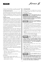
5.2 Electrical connection
The electrical connection must be made by a
qualified electrician and comply with
applicable local standards.
REMARK
: To guarantee availability of the pump
functions it is recommended not to connect the pump
to the boiler controller.
The pump has a power reserve of approx. 3 hours after
power failure. The power reserve only becomes active
after 24 hours of operation when first installed.
- The electrical connection must be carried out via a
fixed connection cable fitted with a coupler or all-
pole switch with a contact opening width of at least
3 mm.
- To ensure that the PG connector is protected from
dripping water and has sufficient strain relief, be sure
to use a connection cable with adequate outer
diameter (e.g. H 05 W-F 3 G1,5).
- Check the current type and voltage of the mains
supply.
- Observe the information on the type plate for the
pump.
- Connect the mains supply to the pump in
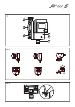
accordance with the connection diagram (
FIG. 3
).
- Release the screw (
FIG. 1 - item 5
) and remove the
terminal box cover (
FIG. 1 - item 6
). The terminal rail
shows the designations of the connections.
- Observe earthing regulations.
- Once connected, close and screw down the
terminal box cover.
6. STARTING UP
6.1 Filling, degassing
- Fill the system properly. The pump rotor chamber is
automatically ventilated after a short period of
operation. Short periods of dry running do not
damage the pump.
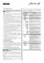
6.2 Operation and adjustment of the pump
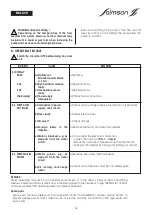
Risk of damage to the pump ! Do not
clean the display window with corrosive
fluids !
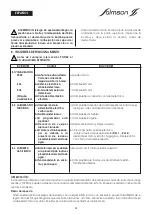
The current time must be set when the circulating
pump is connected to the mains supply for the first
time. See ”Setting the time”.
REMARK
: The pump runs in continuous mode until all
of the switch parameters have been set.
Factory settings
: 24 h continuous operation, no
temperature setting, the routine for recognition and
support of boiler thermal disinfection switching is
switched off (Thermal Disinfection: off).
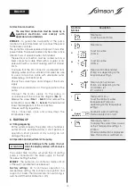
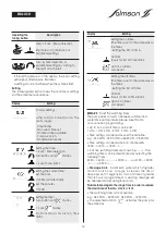
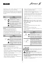
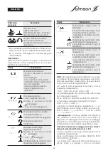
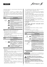
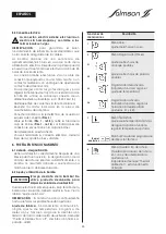
Functions/
Description
Symbols
Time menu :
To set the current time.
Timer menu :
To set 3 possible
on time.
To set 3 possible
off time.
Timer function deactivated.
(Pump runs depending on the
temperature setting).
Timer function activated.
(Pump runs depending on the
on/off times set
(2.1 and 2.2).
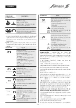
Thermostat menu :
To set the minimum water
temperature (Pump runs
depending on the temperature
setting).
Routine to support switching
thermal disinfection on/off.
Time display menu :
To display the current time, as well
as the 3 temperature settings in
rotation.
If thermal disinfection is displayed
here, this function is switched on.
ENGLISH
ATTENTION !
1
2
2.1
2.2
2.3
2.4
3
4
3.1
Thermal
disinfection
Summary of Contents for THERMO'CLOCK
Page 2: ...2...
Page 3: ...3...
Page 4: ...4 3 5 6 1 4 2 FIG 1 FIG 2 FIG 3...
Page 29: ...29 NOTES...
Page 30: ...30 NOTES...
Page 31: ...31 NOTES...


