


ENGLISH
16
oiler
to
avoid
damages
during
following
operations.
•
Pump
casing
can
be
kept
fastened
to
pipe
work.
•
Remove
motor
fastening
screws
and
move
the
motor
so
that
there
is
enough
space
to
remove
the
back
pull
‐
out
assembly.
When
using
a
coupling
with
spacer
part,
it
is
not
necessary
to
move
the
motor
rearward.
•
Dismantle
coupling
guard,
half
coupling
on
pump
side
and
pump
foot
from
bearing
housing.
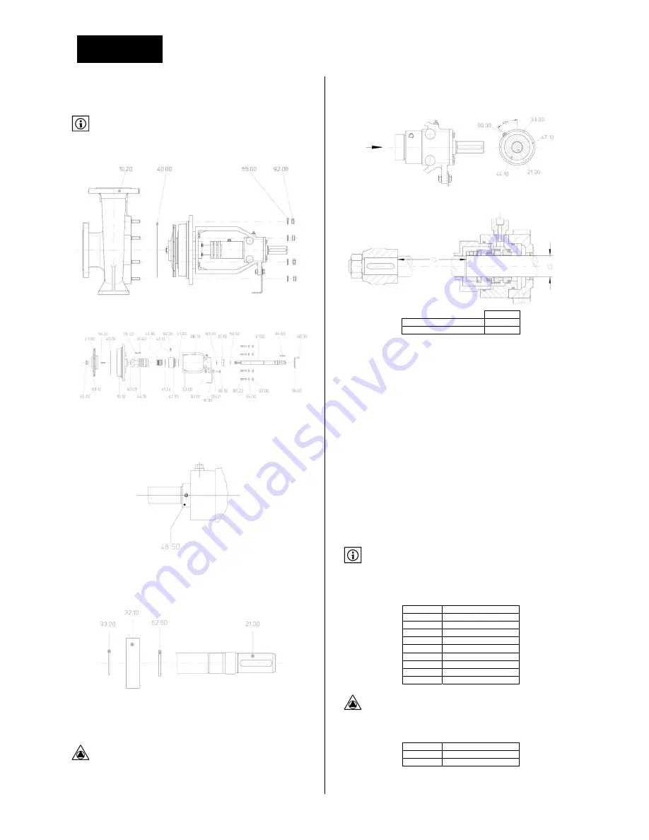
1.
Loosen
nuts
92.00
and
remove
washers
55.00.
2.
Remove
back
pull
out
assembly
from
casing
10.20
and
take
casing
seal
40.00
apart.
3.
Loosen
nut
92.20
and
remove
lock
washer
93.10.
4.
Remove
impeller
23.00
and
key
94.01.
5.
Remove
screws
90.13
from
bearing
bracket
33.00
and
remove
casing
cover
16.10
with
the
sealing
housing
44.10.
It
is
not
necessary
to
dismantle
the
cover
47.10.
6.
Mark
the
position
of
stop
ring
48.50
on
the
shaft.
7.
Remove
mechanical
seal
43.30
with
care.
8.
If
needed
the
housing
44.10
can
be
removed
:
loosen
screws
91.40
and
washers
55.02.
Pull
out
the
cover
47.10
from
bearing
bracket
33.00.
9.
Remove
key
94.00,
loosen
screws
90.10
and
remove
cover
36.00.
10.
Slide
out
shaft
21.00
with
the
ball
bearing
32.10
from
bearing
bracket
33.00.
11.
Remove
circlip
93.20,
ball
bearing
32.10
and
spacing
ring
52.50
from
the
shaft
21.00.
9.3.2
RE
‐
ASSEMBLY
Refer
to
tightening
torques
table
for
screws
and
bolts.
Never
use
grease
:
EPDM
seals
inside
!
All
pumps
parts
should
be
cleaned
before
assembly.
Silicon
based
lubricant
or
glycol,
glycerin
or
water
with
soap
can
be
used
to
ease
assembly
of
gaskets.
Don’t
add
lubricant
on
flat
gaskets.
1.
Slide
ball
bearing
onto
the
shaft.
2.
Assemble
bearing
bracket
and
place
cover
47.10
with
the
vent
screw
90.30
as
shown.
Then
fasten
bearing
bracket
33.00.
.
Positioning
the
mechanical
seal
on
the
shaft
:
Size
a
Shaft
dia.25
175,5
Shaft
dia.
35
237
3.
Place
the
gasket
40.00.
4.
Assemble
back
pull
out
assembly
into
the
casing.
9.3.3
MOTOR
In
order
to
ensure
an
optimum
lifetime
of
the
integrated
motor
a
minimum
maintenance
is
necessary
:
clean
cooling
fins
regularly,
check
coupling
alignment
(if
any),
check
cable
gland
tightening,
…
Ball
bearing
lifetime
depends
on
axial
and
radial
forces
applied
on
motor
shaft
therefore
on
the
pump
design
(close
‐
coupled
pump,
pump
sets
with
elastic
coupling,
…).
Motor
can
be
fitted
with
lifetime
lubricated
ball
bearings
(identified
ZZ
or
2Z)
or
greased.
Greasing
nipples
are
located
at
the
ball
bearings
and
re
‐
greasing
quantities
are
indicated
on
motor
nameplate.
See
motor
instructions
manual
to
find
data
about
maintenance
work
to
be
performed.
9.4
TIGHTENING
TORQUES
Tightening
torques
depend
on
the
material
used
in
the
assembly
and
on
the
type
of
lubricant
that
is
used.
Refer
to
applicable
regulation
to
know
the
tightening
torques
for
the
fastening
of
cast
iron
or
stainless
steel
made
flanges.
The
values
given
below
should
be
only
indicative.
If
real
tightening
torques
are
required
please
ask
our
technical
services.
Threads
Tightening
torques
M6
8,5
Nm
M8
12
Nm
M10
25
Nm
M12
40
Nm
M16
90
Nm
M20
175
Nm
M24
300
Nm
M30
500
Nm
M36
700
Nm
Stainless
steel
bolts
:
apply
anti
‐
fretting
paste
before
assembly.
Tightening
torque
for
back
cover
fastening
nuts
92.00
:
Thread
Tightening
torque
M12
65
Nm
M16
130
Nm
Summary of Contents for NFCH series
Page 2: ...NFCH INSTALLATION ET MISE EN SERVICE FRAN AIS N M S n 4095251 Ed 3 10 13...
Page 23: ...FRAN AIS 23 13 DECLARATION CE...
Page 24: ...NFCH INSTALLATION AND OPERATING INSTRUCTIONS ENGLISH N M S n 4095251 Ed 3 10 13...
Page 25: ...2...


