24
•
The following critical alarms do not allow deactivating
the own acoustic alarm:
Low battery, Fan fault, internal Over temperature in the equip-
ment and battery fault or damaged.
•
The acoustic alarm can be deactivated when beeping,
but it will be activated again as soon as a new alarm
is triggered.
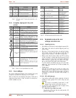
6.1.2. Acoustic alarms.
Code
Condition
Modulation
Alarm silent function
BATT
Warning
Every 4 sec.
It can be silenced
BTOP
Warning
Every 1 sec.
It can be silenced
TEST
Warning
Every 2 sec.
It can be silenced
OPVH
Fault
Continuous
It can be silenced
OPVL
Fault
Continuous
It can be silenced
OPST
Fault
Continuous
It can be silenced
OVLD
Warning
Every 1 sec.
It can be silenced
BATH
Warning
Continuous
It can be silenced
BATL
Warning
Every 1 sec.
It can't be silenced
OVTP
Warning
Every 1 sec.
It can't be silenced
OVTP
Fault
Continuous
It can't be silenced. It is silenced
when temperature decreases.
FNLK
Fault
Continuous
It can't be silenced. It is silences
whtn fan works.
BTWK
Warning
Continuous
It can be silenced
Tabla 7.
Acoustic alarms. Condition and modulation.
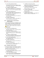
6.1.3. UPS status and colour of the LCD
panel, depending on the condition.
By means of an abbreviated chain of 3 to 4 characters (code), in
the LCD panel is displayed the status of the equipment.
The following table 8 shows the corresponding description to
each letter sequence or chain.
Code
Condition
Description
LCD colour
STBY
Status
UPS working on Standby.
Blue
IPVL
Status
Input voltage too low.
Blue
IPVH
Status
Input voltage too high.
Blue
IPFL
Status
Input frequency too low.
Blue
IPFH
Status
Input frequency too high.
Blue
NORM
Status
UPS working on line mode.
Blue
AVR
Status
UPS working on stabilizer mode.
Blue
BATT
Warning
UPS working on battery mode.
Blue
BTOP
Warning
Battery disconnected.
Red
TEST
Warning
UPS working on battery in life / function
test.
Blue
OPVH
Fault
Battery mode with output voltage too
high.
Red
OPVL
Fault
Output voltage is too low.
Red
OPST
Fault
Short-circuit at the output.
Red
OVLD
Warning
Overload.
Red
BATH
Warning
Battery voltage is too high.
Red
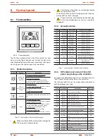
6. Control panel.
6.1. Functionalities.
Fig. 12.
Control panel view.
The UPS has a graphic screen with LCD panel with four keys
and to colour backlight, blue and red. It is used the blue colour
as backlight with black text. When any critical alarm of the equip-
ment is triggered, the light changes to red (see table 8).
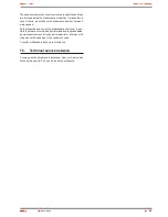
6.1.1. Button functions.
Button
Function
Description
Start up and
shutdown
ON / OFF
To start up or shutdown the equipment:
Press the key for more than 3 sec..
To escape from fault mode:
Turn off the input protection from mains or
unplug the schucko plug from the wall outlet
and press this key for more than 2 seconds.
UPS test.
acoustoc alarm
silencer
To do a battery test:
Hold this key pressed for more than 3 seconds.
To do the battery lifetime test:
Hold this key pressed for more than 10
seconds.
To deactivate the acoustic alarm:
Press this key for one seconde.
Selection
Press this key to select the setting value, one by
one.
Enter
Enter into the setting mode:
Hold this key pressed for more than 3 seconds.
Introducir la opción de ajuste:
Hold this key pressed for more than 1 second.
The equipment allows setting the blinking
parameters and the characters chain.
Confirm settings:
Hold this key pressed for 1 second.
Escape from setting mode:
Hold this key pressed for 3 seconds or the key
ON/OFF for 0,5 seconds.
Tabla 6.
Functionality of the control panel keypad.
•
Make sure that batteries are completely charged be-
fore doing any corresponding test.
USER MANUAL


