12
3.3. Description and operating
principle.
This user's manual describes the installation and operating of
the Uninterruptible Power Supply (UPS) from
SPS.ADVANCE
RT series
, for power ranges between 750 and 3000VA.
These Line-interactive equipments with pure sinewave output,
are designed to protect the most critical electronic devices
against problems of the power supply like undervoltages, peaks,
brownouts, noise in the line and electrical mains fault.
Among other applications, we can quote, PCs, servers, worksta-
tions, and other IT networks devices.
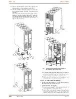
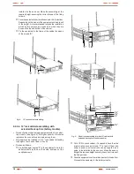
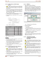
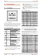
The design allows both the rack-mounting assembling with 2U
height to be fitted in 19" cabinet, previous installation of the side
metallic support with L shape and tower format by using the
plastic supports as a plinth.
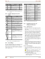
The UPS has a front panel with LCD and four buttons (Start up
switch , Silent/UPS test, Setting and Enter) allow an easy moni-
toring: Configuration and control, AC input line, inform about the
wiring fault and the load status. It also includes two LCD bar graphs,
one indicates the battery charge level and the other one the level of
the load connected at its output. Each bar is divided into five parts,
which each one is equivalent to 20% of the total value.
The equipment has four acoustic alarms (Back up time mode
-discharge of the battery-, low battery - end of back up time-,
overload and UPS fault). By means of the Silent/UPS test button
located at the front panel, the acoustic alarm can be deactivated
or to initiated the autotest procedure.
The
SPS.ADVANCE RT
equipments are fed from AC commer-
cial mains and supply AC energy at their output through the IEC
outlets installed at the rear side of the equipment. In case the
power supply is correct, the load/s are fed through the stabilizer
with «Boost» and «Buck» technology.
In case of mains fault or voltage and/or frequency out of the ac-
ceptable range, load/s will be fed from the batteries through the
inverter for a determined time, depending on the model, battery
charge level and the own load connected at the output.
For models higher than 1000 VA, it is possible to increase the
standard back up time of the equipments, by connecting additional
modules and/or to optimise the recharging time of the accumula-
tors, by fitting chargers with better quality performances (B1).
All the power range has serial and USB communication ports for
communication and equipment control. The serial port supports
the direct communications with a server and the protocol is ac-
cording to a RS-232 interface.
Also, all models have RJ-45 connectors for modem / ADSL / Fax
line protection.
Likewise, the models over 1000 VA have:
•
EPO connector, to install the option and external by the own
user, of an emergency power off button.
•
Smart slot to install one of the following communication cards:
AS-400 relay interface, with DB9 connection.
SNMP for controlling the equipment via Web.
Card for Internet or Intranet management.
This manual is applicable to the standardized and stated models
in table 2.
3.3.1. Main features.
•
Control by microprocessor with high reliability.
•
Design of high frequency.
•
Stabilizer with «Boost» and «Buck» technology.
•
Selectable output range and line sensitivity.
•
Cold start.
•
Standard communication ports: RS-232 and USB.
•
Possible communication extend through the slot.
•
Extended back up time by means of the battery modules for
models higher than 1000 VA.
•
As an option, more powerful battery chargers, for models
higher than 1000 VA.
•
Protection against overload, short-circuit and overtempera-
ture.
•
Design 2 in 1, as 19" rack with 2 U height or Tower.
Model
Type
SPS.750.ADV RT
Standard
SPS.1000.ADV RT
SPS.1500.ADV RT
SPS.2000.ADV RT
SPS.3000.ADV RT
SPS.1500.ADV RT (B0)
No batteries
SPS.2000.ADV RT (B0)
SPS.3000.ADV RT (B0)
SPS.1500.ADV RT (B1)
Large back up time with additional
charger
SPS.2000.ADV RT (B1)
SPS.3000.ADV RT (B1)
Tabla 2.
Standardised models.
3.4. Options.
Depending on the selected configuration, the equipment can in-
clude any of the following options:
USER MANUAL


