18
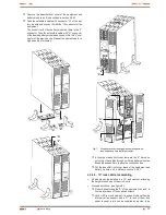
installed by the end user. Make the assembling at the
required height, assuring the correct torque of the fixing
screws.
Face the equipment over the rails and enter it to the bottom.
Depending on the model of the equipment and as a result
of the weight, it is recommended to make the installation
works by two persons, and even more when they are
done on the top and bottom of the cabinet.
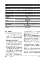
Fix the equipment to the frame of the cabinet by means
of the screws "B".
"A"
"C"
"B"
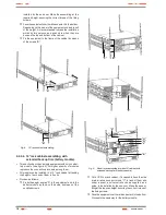
Fig. 8.
19" rack cabinet assembling.
4.2.4.6. 19" rack cabinet assembling, with
extended back up time (battery module).
•
This section describes a single equipment with only one bat-
tery module (see figure 9). For higher quantity of modules
reproduce the connection procedure among them.
•
All models can be installed in a 19" rack cabinet, attending
the height of each one of them is 2 units.
•
Proceed as follows:
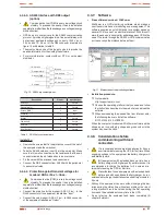
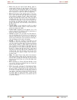
Fix both adaptor angles "A" to the equipment and to the
battery module as rack, on their side, by means of the
supplied screws.
"C"
"B"
"F"
"G"
"J"
"K"
"K"
"H"
Fig. 9.
Model in rack-mounting format in 19" cabinet, with
extended back up time (battery module).
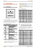
Put a UPS in a rack cabinet, it is needed to have the side
internal rails as support mode "C". In lack of them and
under request, a universal rails can be supplied as a
guide, to be installed by the end user. Make the assem-
bling at the required height, assuring the correct torque of
the fixing screws.
Face the equipment over the rails and enter it to the bottom.
Proceed in the same way for the battery module.
USER MANUAL


