


27
OwnersManual-TileSaw-CTC705-Rev11-2023
Main Causes of Belt Failures:
Premature
Belt
failure
can
be
attributed
to
the
following
issues:
Tension
(too
much
or
too
little),
Pulley
Misalignment,
Damaged
Pulleys,
Improper
Handling
or
Storage,
Incorrect
Blade
Specification
for
Material
Being
Cut,
and
Cutting
Too
Deep.
Symptom
Possible
Cause
Corrective
Action
Belt
Breakage
Too
Much
Tension
Re
‐
tension
Belts
Excessive
Shock
Load
Reduce
Load/
Check
Blade
Specification
Pulley
Out
Of
Round
Replace
Pulley
Burning
of
Belt
Too
Little
Belt
Tension
Increase
Belt
Tension
Excessive
Load
(Cutting
Full
Depth)
For
Best
Performance
Only
Cut
only
1
‐
/2”
to
2”
Per
Pass
Containments
On
Belts
Replace
Belts
and
Find
Source
of
Containments
Incorrect
Blade
Specification
Replace
Blade
with
One
Designed
For
Material
Being
Cut
Symptom
Possible
Cause
Corrective
Action
Belt
Tearing/Ripping
Pulley
Misalignment
Align
Pulleys
Belt
Rolling
Off
Pulley
Pulley
Misalignment
Align
Pulleys
Belt
Cracking
Extremely
Low
Temperature
at
Startup
Warm
Machine
Before
Use
Exposure
To
Chemicals
or
Lubricates
Locate
Source
of
Containments
and
Replace
Belts.
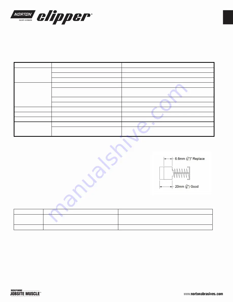
Brush Replacement
Brushes will wear with usage and is part of the machine’s basic
maintenance.
Replace the brushes when the motor begins to lose
power. Brushes typically need to be replaced During the life of the
saw. Replace the brushes when the motor begins to lose power,
or if the motor has gotten wet, or the motor is slow to get up to
speed, or any strange noises come from the motor, or if the motor
is experiencing internal sparking. Replace the brushes when the
length reaches 6.6mm (1/4”). It is normal for the brushes to wear with usage.
UPC
Description NOTES
70184683358 CARBON BRUSHES CTC705 (2)
Set of two (2) Brushes
Dimensions :13mm (H) x 6.25mm (T) x 20mm (L)
70184683359 BRUSH CAP (1) 705
Sold as EACH
SAW MAINTENANCE &
TROUBLE SHOOTING


