2
1
6
3
4
9
5
8
7
2
2
1
A
84
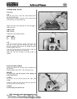
CAMSHAFT REMOVAL
Remove the spark plug (1).
Loosen the 6 mm bolt (2) and tap it to lift the left side cover.
Remove the left side cover (3) and gasket (4).
Remove the left crankcase cover.
Remove the cam chain tensioner sealing bolt, spring and
tensioner push rod.
Turn the fl ywheel counterclockwise until the "O" mark (5) on the
cam sprocket aligns with cut-out (6) on the cylinder head.
Remove the cam sprocket bolts (7) and dowel pin (8).
Remove the cam sprocket (9).
NOTE
Suspend the cam chain with a piece of wire (A) to prevent it
from falling into the cylinder head.
Remove the valve adjuster covers and loosen the valve
adjusters completely.
Screw the cam sprocket bolts into the camshaft and pull out the
camshaft (1) while holding the rocker arms.
NOTE
Cylinder head can be removed with the camshaft installed on
the cylinder head.
INSPECTION
Turn the outer race of the camshaft bearing (2) with fi nger.
The outer race should turn smoothly and quietly.
Also check that the bearing inner race fi ts tightly on the
camshaft.
Replace the camshaft bearing if the outer race does not turn
smoothly, quietly, or if it fi ts loosely on the camshaft.
Check each cam lobe for wear or damage.
Measure the cam lobe height.
SERVICE LIMITS:
IN: 18.705 mm
EX: 18.697 mm
CYLINDER HEAD / VALVES
Summary of Contents for madass
Page 53: ...50 LUBRICATION SYSTEM...
Page 111: ...10 12 Nm 10 14 Nm 108 CYLINDER PISTON...
Page 112: ...109 ZYLINDER KOLBEN...
Page 129: ...1 2 126 CLUTCH GEARSHIFT LINKAGE Remove the primary drive clutch 1 and clutch center guide 2...
Page 191: ...PICK UP KILL SWITCH RPM STOP B R G G G Bl W 188 IGNITION SYSTEM SCHEMA...
Page 192: ...PICK UP KILLSCHALTER DREHZAHLBEGRENZER Z NDANGLEICHER B R G G G Bl W 189 Z NDSYSTEM DIAGRAM...


