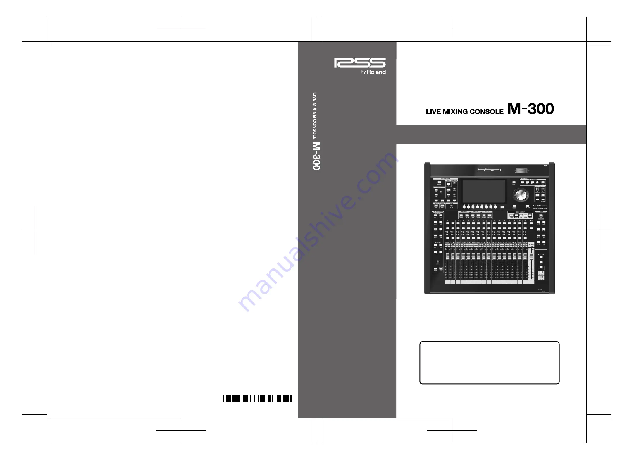
background image

Copyright © 2010 ROLAND CORPORATION

All rights reserved. No part of this publication may be reproduced in any form 

without the written permission of ROLAND CORPORATION.

Owner’s Manual

Owner’s Manual

*

5

1

0

0

0

1

4

6

4

1

-

0

1

*

Before using this unit, carefully read the sections entitled: “IMPORTANT 
SAFETY INSTRUCTIONS” (p. 2), “USING THE UNIT SAFELY” (p. 3–5), and 
“IMPORTANT NOTES” (p. 6–8). These sections provide important 
information concerning the proper operation of the unit. Additionally, in 
order to feel assured that you have gained a good grasp of every feature 
provided by your new unit, Owner’s manual should be read in its entirety. 
The manual should be saved and kept on hand as a convenient reference.

Summary of Contents for M-300

Page 1: ...carefully read the sections entitled IMPORTANT SAFETY INSTRUCTIONS p 2 USING THE UNIT SAFELY p 3 5 and IMPORTANT NOTES p 6 8 These sections provide important information concerning the proper operation of the unit Additionally in order to feel assured that you have gained a good grasp of every feature provided by your new unit Owner s manual should be read in its entirety The manual should be save...

Page 2: ...WN LIVE For the U K CAUTION Danger of explosion if battery is incorrectly replaced Replace only with same or equivalent type WARNING To reduce the risk of fire or electric shock do not expose this apparatus to rain or moisture This product complies with the requirements of EMCD 2004 108 EC and LVD 2006 95 EC For EU Countries For EU Countries Apparatus containing Lithium batteries ADVARSEL Lithiumb...

Page 3: ...e or in combination with an amplifier and headphones or speakers may be capable of producing sound levels that could cause permanent hearing loss Do not operate for a long period of time at a high volume level or at a level that is uncom fortable If you experience any hearing loss or ringing in the ears you should immediately stop using the unit and consult an audiologist 011 Do not allow any obje...

Page 4: ... the use of insecticides perfumes alcohol nail polish spray cans etc near the unit Swiftly wipe away any liquid that spills on the unit using a dry soft cloth 027 Never expose lithium battery to excessive heat such as sunshine fire or the like 101a The unit should be located so that its location or position does not interfere with its proper venti lation 102b Always grasp only the plug on the powe...

Page 5: ...eing swallowed accidentally 120 Always turn the phantom power off when connecting any device other than condenser micro phones that require phantom power You risk causing damage if you mistakenly supply phantom power to dynamic microphones audio playback devices or other devices that don t require such power Be sure to check the specifications of any microphone you intend to use by referring to th...

Page 6: ...uch problems you should relocate such wireless devices so they are at a greater distance from this unit or switch them off 354a Do not expose the unit to direct sunlight place it near devices that radiate heat leave it inside an enclosed vehicle or otherwise subject it to temperature extremes Excessive heat can deform or discolor the unit 355b When moved from one location to another where the temp...

Page 7: ...les that incorporate resistors for connecting to this unit The use of such cables can cause the sound level to be extremely low or impossible to hear For information on cable specifications contact the manufacturer of the cable Before Using USB memory Using USB memory 704 Carefully insert the USB memory card all the way in until it is firmly in place 705 Never touch the terminals of the USB memory...

Page 8: ...y law 852a This product can be used to record or duplicate audio or visual material without being limited by certain technological copy protection measures This is due to the fact that this product is intended to be used for the purpose of producing original music or video material and is therefore designed so that material that does not infringe copyrights belonging to others for example your own...

Page 9: ... CHANNEL DISPLAY screen 44 Stereo linking channels 49 Specifying a channel name and color label 50 Copying channel settings to another channel 51 Using the channel library 52 Assigning channels to DCA groups and MUTE groups 53 AUX MTX MAIN operations 54 About AUX MTX MAIN 54 Operations using the CHANNEL EDIT section 55 Operations in the CHANNEL DISPLAY screen 58 Stereo linking AUX MTX 63 Linking M...

Page 10: ...ing an external effects device 106 Inserting an external effects device into a channel 107 DCA groups 108 About DCA groups 108 DCA group settings 108 Assigning a channel to a DCA group 108 Specifying a name and color label for the DCA group 109 Using the panel to control DCA groups 109 Mute groups 110 About mute groups 110 Assigning a channel to a mute group 110 Specifying a name and color label f...

Page 11: ...xer settings 155 Date time settings 158 Managing USB memory 159 Console Lock 162 Help function 163 Other settings 164 Management of the M 48 live personal mixer 166 What is the M 48 live personal mixer 166 Connecting M 48 units to the M 300 167 Editing and managing M 48 units 168 Specifying the outputs from the M 300 to the M 48 unit 169 Viewing the connected M 48 units 170 Making settings for an ...

Page 12: ...12 Pitch shift 212 GEQ 213 Roland vintage effects 214 Index 216 Screen index 220 M 300_e book 12 ページ 2010年4月22日 木曜日 午前8時17分 ...

Page 13: ...T In the case of function buttons the function is given in parentheses such as F1 LINK The REAC Roland Ethernet Audio Communication interface is the core of this system It uses a proprietary protocol based on Ethernet technology and allows 40 channels of digital audio to be sent in each direction via a single Cat5e Ethernet cable REAC can do the following Send 40 channels of digital audio in each ...

Page 14: ...the REAC mode of the other must be set to REAC slave In this system the M 300 is normally set to be the master FOH setting while the input output units are set to be slaves For a more detailed description of connections refer to REAC applications p 138 Cat5e Ethernet cables up to 100 meters long are supported If you need a longer connection we recommend that you use the optional S OPT fig connect ...

Page 15: ...rt When the M 300 is shipped from the factory REAC caps are attached to the REAC ports In order to use REAC port you ll need to remove the REAC cap Take care not to lose the REAC caps you remove fig connection eps When using an Ethernet cable with standard RJ45 plugs fit the included REAC connector covers on the REAC ports as shown fig REAC cover inst3 eps Remove the REAC connector cover if you re...

Page 16: ... supply Use only the supplied power cords to prevent damage to the units 1 As shown in the illustration fit the power cord hook over the power cord fig cord hook1 eps When installing in a Rack the M 300 should be used only with the optional rackmount angle brackets RA 10U AC power connections Attaching the power cord hook When installing in a Rack M 300_e book 16 ページ 2010年4月22日 木曜日 午前8時17分 ...

Page 17: ...on refer to the owner s manual of the S 0808 6 Turn on the power of the equipment connected to the audio outputs of the M 300 and your input output units 942 This unit is equipped with a protection circuit A brief interval a few seconds after power up is required before the unit will operate normally 1 Mute the outputs using F6 MUTE ALL OUT in the MUTE GROUP screen p 110 2 Turn off the power of th...

Page 18: ...ou backed up the data in step 1 p 156 Le M 300 est équipé d une pile au lithium qui fait fonctionner l horloge et préserve les réglages du mélangeur Si la pile est faible l horloge et la restauration des réglages du mélangeur ne fonctionnent pas correctement Si un message contextuel recommandant de remplacer la pile s affiche lorsque l appareil est mis sous tension il faut la remplacer comme suit ...

Page 19: ...nternal mixer data Carefully insert the USB memory all the way in until it is firmly in place USB memory used with the USB Memory Recorder must support USB 2 0 Hi speed The USB memory connector is fitted with a USB memory cover When using USB memory open the USB memory cover When not using USB memory keep the USB memory cover closed battery panel1 eps About the USB memory cover M 300_e book 19 ページ...

Page 20: ...on section p 25 Screen controller section p 25 METER button p 25 EFFECTS Section p 25 GROUP section p 26 SETUP Section p 26 SCENE MEMORY section p 26 USB MEMORY RECORDER section p 26 TALKBACK OSC Section p 27 MONITOR Section p 27 USER Section p 27 PHONES jack p 27 PHONES LEVEL knob p 27 2 1 3 4 5 6 7 10 11 12 13 14 15 16 18 9 8 17 1 2 3 4 5 6 7 8 9 10 11 12 13 14 15 16 17 18 M 300_e book 20 ページ 20...

Page 21: ...hannel The button will be lit if mute is active Faders These adjust the signal level of each channel fig LayerSectGuide eps This section lets you select the channel layer that will be assigned to the fader module section The button of the currently assigned channel layer will be lit USER1 layer button USER2 layer button This assigns the user fader layer 1 or user fader layer 2 to the fader module ...

Page 22: ...IN C channels SOLO button This button turns solo on off for the MAIN L R C channels It will light if solo is on Fader This adjusts the signal level of the MAIN L R C channels fig ChEditSectGuide eps In this section you can operate the main parameters of the currently selected channel CH DISP button This button accesses the CHANNEL DISPLAY screen It will light red while this screen is displayed fig...

Page 23: ... It will light if the EQ is on Band selection button LO LO MID HI MID HI These buttons select the band controlled by knobs on the EQUALIZER area The button of the currently selected band will light For AUX1 8 MTX1 4 or MAIN L R C HI MID HI buttons move the target band of the 8 band EQ on screen For details refer to 8 band EQ operations AUX MTX MAIN p 82 Q knob This adjusts the Q of the selected ba...

Page 24: ... adjust the send level from CH1 32 to the AUX MTX buses or adjust the send level from AUX1 8 MAIN L R C to the MTX buses AUX1 AUX8 MTX1 MTX4 buttons These buttons select the AUX MTX bus that will be the target of the SEND LEVEL knob or the faders in SENDS ON FADER mode You can turn the corresponding send switch on off by holding down SHIFT and pressing AUX1 AUX8 MTX1 MTX4 DISP button This button a...

Page 25: ...ou to adjust the setting in finer detail You can use the user preference SHIFT LOCK p 137 to change the behavior of the SHIFT button ENTER button Use this button to turn an on screen button on off or to confirm a change you ve made to the settings HELP button This button accesses the HELP CONTENTS popup If you hold down HELP and press another button an explanation of that button will appear in the...

Page 26: ...ng or following song During playback button takes you back to the beginning of the currently playing song Rewinding or fast forwarding during playback By pressing and holding these buttons while a song is playing you can rewind or fast forward Normal playback will resume when you release the button button Use this button to start or stop playback or to start recording Playing a song When you press...

Page 27: ...of all channels in a single operation fig UserSectGuide eps DISP button This button accesses the USER screen where you can change or edit the user settings It will light red while the screen is shown If you hold down SHIFT and press this button the USER BUTTON tab of the USER PREFERENCE popup will appear This is a convenient way to check the user button settings USER 1 8 button These access the fu...

Page 28: ...tor p 30 MIDI connectors p 30 RS 232C MIDI select switch p 30 RS 232C connector p 30 DIGITAL OUT jack p 31 Security slot p 31 BATTERY slot p 31 Grounding terminal p 31 Power cord hook p 31 AC INPUT connector p 31 POWER switch p 31 USB MEMORY connector p 31 2 1 3 4 5 6 7 10 11 12 13 14 15 9 8 1 2 3 4 5 6 7 8 9 10 11 12 13 14 15 M 300_e book 28 ページ 2010年4月22日 木曜日 午前8時17分 ...

Page 29: ... volume level of equipment connected to the inputs CONSOLE INPUT may be low If this happens use connection cables that do not contain resistors fig ConsOutJackGuide eps CONSOLE OUTPUT 1 4 These are balanced XLR 3 32 male output jacks for outputting analog audio signals By default MAIN L R MONITOR L R are patched to them 922 Wiring diagrams for these jacks are shown below Make connections after fir...

Page 30: ...ion and an OUT THRU connector for transmission and thru are provided You can use the REMOTE popup to switch between the OUT and THRU functions For details refer to MIDI settings p 149 fig SerialSelSWGuide eps On the M 300 you can use either the MIDI connectors or the RS 232C connector This switch selects the connector s you will use You must switch off the M 300 s power before changing the positio...

Page 31: ...ectrical charge which is absolutely harmless However if you are concerned about this connect the ground terminal see figure with an external ground When the unit is grounded a slight hum may occur depending on the particulars of your installation If you are unsure of the connection method contact the nearest Roland Service Center or an authorized Roland distributor as listed on the Information pag...

Page 32: ...crChDisp eps You can make adjustments in finer increments by holding down SHIFT while you operate the CHANNEL EDIT section s knobs or the value dial If you want to edit channel parameters that are not shown in the CHANNEL DISPLAY screen you can press the DISP button in each area of the CHANNEL EDIT section to access a popup that lets you make settings in greater detail If you ve selected the CHANN...

Page 33: ...he button that turned red when you pressed it to access a screen Buttons that access a popup are excepted A user setting lets you choose either the CHANNEL DISPLAY screen or the METER screen as the Home screen For details on how to choose the Home screen refer to Editing other user preferences p 137 Accessing a screen Home screen CHANNEL DISPLAY screen AUX MTX SENDS popup SCENE screen HELP CONTENT...

Page 34: ...tting indication This shows the current user settings Scene indication This shows the number and name of the currently selected scene Main display area fig ScrMainArea eps Most screen operations are performed in this area The name of the current screen is shown in the screen name indication of the top display area You can use the cursor and function buttons to perform operations in this area Main ...

Page 35: ... a cursor and function buttons for performing operations in the screen fig Popups eps While a popup is displayed cursor and function button operations are valid only for the popup fig FuncBtnGuide eps The function buttons are assigned to the main display area of the screen or the popup and are operated using F1 F8 There are three types of function buttons as follows Command function buttons fig Fu...

Page 36: ...g BtnAllClr eps These buttons assist you in operating check buttons Pressing the ALL button will select all applicable check buttons Pressing the CLR button will clear all applicable check buttons fig Cursor eps Knobs in the screen can be operated by the knobs of the CHANNEL EDIT section or by the value dial To use the value dial move the cursor to the desired knob You can make more detailed setti...

Page 37: ...r location between uppercase and lowercase If the character is not an English letter it will be changed to the letter A F3 NUM Converts the character at the cursor location to the numeral 0 F4 DELETE Deletes the character at the cursor location The text at the right of the cursor location will move to the left F7 CANCEL Cancels any changes and closes the popup F8 OK Confirms the changes and closes...

Page 38: ...ssage will not appear in step 7 1 Access the desired LIBRARY popup fig ScrChLib eps 2 Make sure that the applicable channel effect indication shows the object that you want to recall 3 Select the desired library data in the library data list 4 Press F4 RECALL fig ScrLibRecallConf eps A message will ask you to confirm the operation 5 Press F8 RECALL to execute the library recall operation and close...

Page 39: ...ary data list select the desired library data You cannot clear library data in which PRESET or LOCK is shown 3 Press F6 CLEAR fig ScrM48LibDel_Conf eps A message will ask you to confirm the operation 4 Press F8 CLEAR The library data you selected in step 2 will be cleared Pressing F7 CANCEL will cancel the operation N CONFIRMATION message fig Confirm eps This message asks you to confirm an operati...

Page 40: ...t level in the digital domain HPF High pass filter This is a 12 dB octave filter that passes the region higher than the specified frequency GATE EXPANDER This is a dynamics processor that can be used as a gate expander or ducking COMPRESSOR This is a dynamics processor that can be used as a compressor EXT FX INSERT External effect insert An external effects processor can be inserted at this point ...

Page 41: ...nel that you want to edit fig SELBtn eps 2 The selected channel is shown in the channel indication at the upper center of the screen fig ScrTBChDisp eps 1 In the CHANNEL EDIT section press CH DISP The CHANNEL DISPLAY screen will appear fig ScrChDisp eps Selecting the channel to edit SEL Viewing the parameter values Even if you don t access the CHANNEL DISPLAY screen the value of the currently oper...

Page 42: ...f pad is on the PAD button will light Since noise will be produced when you switch the pad setting the output of the channel whose setting you change will be briefly muted Turn the pad on if the input level is too high even when the preamp gain is set to the minimum position Use the HPF area of the CHANNEL EDIT section to operate the filter fig ChEdtFilter eps 1 Press ON to turn the HPF on off Use...

Page 43: ...knob Use the AUX MTX SENDS area of the CHANNEL EDIT section to perform these operations fig ChEdtAux eps You can adjust the send level in either of two ways using the SEND LEVEL knob of the AUX SENDS area or using the faders of the top panel Using the SEND LEVEL knob 1 Press AUX1 AUX8 MTX1 MTX4 to select the send destination AUX MTX bus 2 Use the SEND LEVEL encoder to adjust the amount sent to the...

Page 44: ...ced when you switch the phantom power setting the output of the channel whose setting you change will be briefly muted PAD button This turns the pad on off Turning this on will lower the input sensitivity of the preamp by 20 dB Since noise will be produced when you switch the pad setting the output of the channel whose setting you change will be briefly muted Turn the pad on if the input level is ...

Page 45: ...B 0 0 dB For details refer to Gate expander operations p 68 Compressor fig ScrChComp eps COMP button This turns the compressor on off IN meter This shows the input level of the compressor For stereo linked channels two meters L and R will be shown GR meter This shows the amount of gain reduction for the compressor OL Overload indicator This will light red when the output of the compressor exceeds ...

Page 46: ...tton This turns the 4 band EQ on off 4 band EQ graph This shows the approximate response of the 4 band EQ OL Overload indicator This will light red when the output of the 4 band EQ exceeds the OVER Lev setting specified in the METER SETUP popup p 96 LO shelving button HI shelving button When turn this on LO HI band becomes lo shelving hi shelving Q knobs These adjust the Q of the corresponding ban...

Page 47: ...oportion of the signal that is sent to MAIN C when PAN is at C center as a value in a range of 0 100 This is valid when the LCR button is on fig Pan_LCR eps PAN When LCR button is off This adjusts the left right panning of the audio signal sent to the MAIN L R buses in a range of L63 R63 When LCR button is on This adjusts the left center right panning of the audio signal sent to the MAIN L R C bus...

Page 48: ...IN button This turns the send to the MAIN L R C on off This is shown only when the LCR button is off The function buttons have the following operations The F7 ATT Ctrl setting is common to all channels CH1 32 When the M 300 is configured as a Monitor console it is convenient to use the GAIN knob as an attenuator over the shared inputs The F7 ATT Ctrl setting is stored in the M 300 as a system para...

Page 49: ...o stereo link 2 Press F1 LINK A confirmation message will appear asking you to confirm the stereo link operation The function buttons have the following operations 3 Press F7 LINK L R or F8 LINK L R the channels will be stereo linked The following parameters are linked by stereo link Attenuator HPF Gate expander parameters other than Key In Compressor parameters other than Key In 4 band EQ paramet...

Page 50: ...t the channel name Use the cursor left right buttons to move the cursor location Use the value dial to change the character at the cursor location 3 Press F8 CLOSE to close the popup 1 Access the NAME EDIT popup for the desired channel 2 Move the cursor to the desired color label select button and press ENTER to make your selection 3 Press F8 CLOSE to close the popup Specifying a channel name and ...

Page 51: ... the CHANNEL COPY popup fig ScrChCopyGuide eps Copy source channel This indicates the copy source channel Copy parameter select buttons Here you can select the parameters that will be copied You can select the following parameters Copy destination channel select buttons Here you can select the copy destination channel s The function buttons have the following operations 3 Move the cursor to the de...

Page 52: ... the target of the CHANNEL LIBRARY popup Library data list This is a list of the library data Recall parameter select buttons Use these to select the parameters that will be recalled You can select the following parameters Noise may occur when you execute a library preview or recall but this is not a malfunction The function buttons have the following operations Using the channel library 2 1 3 1 2...

Page 53: ...the channel will be assigned 1 Access the GROUP ASSIGN popup for the desired channel fig ScrChGroupAssign eps 2 Verify that the target channel is correct 3 Move the cursor to the desired DCA group select button and press ENTER to select it 4 Press F8 CLOSE to close the popup For details refer to DCA groups p 108 1 Access the GROUP ASSIGN popup for the desired channel fig ScrChGroupAssign eps 2 Ver...

Page 54: ... MIX MTX SEND 1 4 TO MTX 1 3 TO MTX 2 4 ON SEND MTX LINK PAN ON SEND MTX SEND 1 4 TO MTX 1 3 TO MTX 2 4 ON SEND MTX LINK PAN ON SEND TO MAIN L TO MAIN R TO MAIN C MAIN SEND PAN PAN LCR LR ON MAIN ON CENTER C ON LCR 8 BAND PEQ 8 BAND PEQ 8 BAND PEQ DELAY LIMITER DELAY MONO MIX AFL ON PFL AFL PFL AFL PFL AFL AFL ON AFL ON L R C GR GR GR MAIN SEND F ROM AUX 1 8 MTX SEND F ROM MAIN L C R MTX SEND F RO...

Page 55: ...u press the MAIN SEL button it will select the MAIN L MAIN R or MAIN C one after another 2 The selected channel is shown in the channel indication at the upper center of the screen fig ScrSelectedAux eps 1 In the CHANNEL EDIT section press CH DISP The CHANNEL DISPLAY screen will appear fig ScrChAux eps Selecting the channel to edit SEL SEL Viewing the parameter values Even if you operate the knobs...

Page 56: ...holding down SHIFT while you operate the knob Use the EQUALIZER area of the CHANNEL EDIT section to operate the EQ fig ChEdtEQ eps 1 In the CHANNEL EDIT section press CH DISP fig ScrChAux eps The CHANNEL DISPLAY screen will appear 2 Press ON to turn the 8 band EQ on off 3 User the HI MID HI to select the band 4 Use the GAIN knob to adjust the gain of the selected band 5 Use the FREQ knob to adjust...

Page 57: ... the knob You can t use SENDS ON FADER to adjust the send amount to an MTX bus By pressing DISP you can access the MTX SENDS popup where you can make detailed MTX send settings p 86 Operating on MTX 1 Press SEL of the MTX to select the send destination MTX bus 2 Press AUX1 AUX8 on the AUX MTX SENDS area to select the send source AUX 3 Use the SEND LEVEL knob to adjust the amount of signal sent to ...

Page 58: ...fig ScrChLim eps LIM button This turns the limiter on off IN meter This indicates the input level of the limiter For stereo linked channels two meters L and R are shown GR meter This indicates the amount of gain reduction produced by the limiter OL Overload indicator This will light red when the output of the limiter exceeds the OVER Lev setting specified in the METER SETUP popup p 96 THRE knob Th...

Page 59: ...ERNAL INSERT screen Inserting an external effects processor into a channel is done in the EXTERNAL INSERT screen For details refer to Inserting an EXT FX into a channel p 107 8 band EQ fig ScrChEQ eps EQ button This turns the 8 band EQ on off OL Overload indicator This will light when the output of the 8 band EQ exceeds the OVER Lev setting specified in the METER SETUP popup p 96 8 band EQ graph T...

Page 60: ...N button This turns the send to MAIN L R C This is shown only when the LCR button is on LR button C button These individually turn the send to the MAIN L R and MAIN C on off These are shown only when the LCR button is on CENTER This specifies the proportion of the signal that is sent to MAIN C when PAN is at C center as a value in a range of 0 100 This is valid when the LCR button is on fig Pan_LC...

Page 61: ...crChBal eps This adjusts the left right output balance sent from MAIN L R or stereo linked AUX MTX in a range of L63 R63 Group fig ScrChGroup eps By moving the cursor to DCA GROUP or MUTE GROUP and pressing ENTER you can access the GROUP ASSIGN popup where you can make DCA group and MUTE group assignments You can also access the GROUP ASSIGN popup window by pressing F5 GROUP ASSIGN Fader fig ScrCh...

Page 62: ...5 29 97 30fps F2 NAME EDIT Accesses the NAME EDIT popup where you can specify the channel name p 50 F3 COPY Accesses the AUX MTX MAIN COPY popup where you can copy channel settings p 64 F4 LIBRARY Accesses the AUX MTX MAIN LIBRARY popup where you can use the channel library p 65 F5 GROUP ASSIGN Accesses the GROUP ASSIGN popup where you can make DCA group and MUTE group assignments p 53 F6 PEAK CLE...

Page 63: ...LAY screen for the AUX MTX that you want to stereo link fig ScrChAux eps 2 Press F1 LINK fig ScrAuxLinkConf eps A confirmation message will appear asking you to confirm the stereo link operation The function buttons have the following operations 3 Press F7 LINK L R or F8 LINK L R the AUX MTX will be stereo linked Stereo link will link the following parameters Attenuator Limiter parameters 8 band E...

Page 64: ...olors as the color label Channel name entry and color label selection are done in the NAME EDIT popup For details on NAME EDIT popup refer to Specifying a channel name and color label p 50 Channel settings can be copied to another channel Channel copying is done in the AUX MTX MAIN COPY popup 1 Access the CHANNEL DISPLAY screen or the desired copy source channel ig ScrChAux eps 2 Press F3 COPY to ...

Page 65: ...ary or store the settings of the current channel in the library AUX MTX MAIN library operations are performed in the AUX MTX MAIN LIBRARY popup 1 Access the CHANNEL DISPLAY screen for the desired channel ig ScrChAux eps 2 Press F4 LIBRARY to access the AUX MTX MAIN LIBRARY popup fig ScrChLibOutGuide eps Target channel This indicates the channel that is the target of the AUX MTX MAIN LIBRARY popup ...

Page 66: ... ig ScrChAux eps 2 Press F7 COPY MAIN MIX A confirmation message will ask you to confirm the operation 3 Press F8 OK to copy the send amount from each input channel to MAIN If you press F7 CANCEL the Copy operation will be cancelled In the case of stereo linked AUXes the pan from each input channel to MAIN will also be copied F2 PREVIEW Previews auditions the selected library data F3 NAME EDIT Acc...

Page 67: ... MTX Copy destination channel select button This indicates the copy destination MTX The function buttons perform the following operations 3 Use the copy destination select button to select the copy destination MTX 4 Press F3 PASTE CopyCHoutonf1 eps A confirmation message will ask you to confirm the operation 5 Press F8 PASTE to copy the mix to the MTX you selected in step 3 If you press F7 CANCEL ...

Page 68: ...es a user adjustable level of attenuation RANGE to input signals that are higher than the threshold level fig GateDuck eps Gate expander operations are performed in the GATE EXPANDER popup Gate expander operations INPUT LEVEL TIME OUTPUT LEVEL LEVEL THRESHOLD THRESHOLD RANGE RANGE ATTACK HOLD RELEASE INPUT SIGNAL OUTPUT SIGNAL INPUT LEVEL TIME OUTPUT LEVEL LEVEL THRESHOLD THRESHOLD ATTACK RELEASE ...

Page 69: ... 80 0 dB 0 0 dB RANGE knob This adjusts the RANGE in a range of Inf dB 0 0 dB ATTACK knob This adjusts the ATTACK time in a range of 0 0 ms 800 0 ms This is the time from when the input signal exceeds the threshold level until the gate opens completely RELEASE knob This adjusts the RELEASE time in a range of 0 ms 8000 ms This is the time over which the gate reaches its maximum effect after the HOL...

Page 70: ...de eps THRESH knob This adjusts the threshold level in a range of 80 0 dB 0 0 dB RANGE knob This adjusts the RANGE in a range of Inf dB 0 0 dB ATTACK knob This adjusts the ATTACK time in a range of 0 0 ms 800 0 ms This is the time from when the input signal exceeds the threshold level until the ducking effect reaches its maximum RELEASE knob This adjusts the RELEASE time in a range of 0 ms 8000 ms...

Page 71: ...lowing operations 1 In the fader module section press a SEL button to select the desired channel 2 In the GATE area of the CHANNEL EDIT section press DISP fig PopGate eps The GATE EXPANDER popup will appear BPF Band pass filter Passes the region at the specified frequency HPF High pass filter Passes the region higher than the specified frequency LPF Low pass filter Passes the region below the spec...

Page 72: ... 1 Access the GATE EXPANDER popup fig PopGate eps 2 Use the filter type select buttons to select the filter type 3 Use the FREQ Q knobs in the KEY IN FILTER section to adjust the filter 4 Use the ON button in the KEY IN FILTER section to turn the filter on If you turn F7 KEY IN SOLO on you can hear the output signal of the key in filter via the M 300 s monitor output F7 KEY IN SOLO will automatica...

Page 73: ...e library The GATE EXP LIBRARY popup is used to perform gate expander library operations 1 Access the GATE EXPANDER popup 2 Press F4 LIBRARY to access the GATE EXP LIBRARY popup ffig PopGateLibGuide eps Channel indication This indicates the channel to which the GATE EXPANDER LIBRARY popup applies Library data list This is a list of the library data The function buttons have the following operation...

Page 74: ... meter This indicates the output level of the compressor For stereo linked channels two meters L and R are shown Parameters In this field you can edit the compressor parameters fig PopCompGuide2 eps THRESH knob This adjusts the threshold level in a range of 40 0 dB 0 0 dB RATIO knob This adjusts the RATIO in a range of 1 00 1 INF 1 14 steps ATTACK knob This adjusts the ATTACK time in a range of 0 ...

Page 75: ...ing 6 dB of headroom 1 In the fader module section press a SEL button to select the desired channel 2 In the COMP area of the CHANNEL EDIT section press DISP fig PopComp eps The COMPRESSOR popup will appear Selection Knob Parameter PARAM 1 Q Threshold level FREQ Attack time GAIN Release time PARAM 2 Q Ratio FREQ Knee GAIN Gain BPF Band pass filter Passes the region at the specified frequency HPF H...

Page 76: ...ELF 1 Access the COMPRESSOR popup fig PopComp eps 2 Use the filter type select buttons to select the filter type 3 Use the FREQ Q knobs in the KEY IN FILTER section to adjust the filter 4 Use the ON button in the KEY IN FILTER section to turn the filter on If you turn F7 KEY IN SOLO on you can hear the output signal of the key in filter via the M 300 s monitor output F7 KEY IN SOLO will automatica...

Page 77: ... is used to perform compressor library operations 1 Access the COMPRESSOR popup 2 Press F4 LIBRARY to access the COMP LIBRARY popup fig PopCompLibGuide eps Channel indication This indicates the channel to which the GATE EXPANDER LIBRARY popup applies Library data list This is a list of the library data The function buttons have the following operations For details on library operations refer to Li...

Page 78: ... of the limiter For stereo linked channels two meters L and R are shown Parameters In this field you can edit the compressor parameters fig PopLmtGuide2 eps THRESH knob This adjusts the threshold level in a range of 40 0 dB 0 0 dB ATTACK knob This adjusts the ATTACK time in a range of 0 0 ms 800 0 ms This is the time from when the input signal exceeds the threshold level until the limiter reaches ...

Page 79: ...his indicates the channel to which the GATE EXPANDER LIBRARY popup applies Library data list This is a list of the library data The function buttons have the following operations For details on library operations refer to Library operations p 37 Selection Knob Parameter PARAM 1 Q Threshold level FREQ Attack time GAIN Release time PARAM 2 Q FREQ Knee GAIN F1 LIMITER ON Turns the limiter on off F4 L...

Page 80: ...t the frequency in a range of 20 Hz 20 0 kHz fig FilterCurve eps IN meter This indicates the input level of the 4 band EQ For stereo linked channels two meters L and R are shown 4 band EQ graph This indicates the approximate response of the 4 band EQ OUT meter This indicates the output level of the 4 band EQ For stereo linked channels two meters L and R are shown 4 band EQ parameters fig PopEQPrmG...

Page 81: ...l to which the 4 BAND EQ LIBRARY popup applies Library data list This is a list of the library data Recall parameter select buttons These select the section that will be recalled The function buttons have the following operations For details on library operations refer to Library operations p 37 Noise may occur when you preview or recall a library item but this is not a malfunction F1 HPF ON Turns...

Page 82: ...eaking type filters in a range of 0 36 16 00 Higher values produce a sharper curve The Q knob is not shown in bands 1 8 when LSV HSV is selected as a filter type FREQ knobs This adjusts the center frequency of each band in a range of 20Hz 20 0kHz GAIN knobs This adjusts the gain of each band in a range of 15 0 dB 15 0 dB The GAIN knob is not shown bands 1 8 when HPF LPF is selected as a filter typ...

Page 83: ...dEQLibGuide eps Channel indication This indicates the channel to which the 8 BAND EQ LIBRARY popup applies Library data list This is a list of the library data The function buttons have the following operations For details on library operations refer to Library operations p 37 Noise may occur when you preview or recall a library item but this is not a malfunction Setting the 8 band EQ to a flat st...

Page 84: ...e adjust the sends from the CH to AUX MTX The AUX MTX send area is structured as follows fig PopAuxSendFieldGuide eps Number Name This indicates the AUX MTX number and name Send level bar This adjusts the send level to AUX MTX in a range of InfdB 10 0dB The color of the send level bar indicates the send point or the status of the send switch as follows ON button This turns the send switch on off T...

Page 85: ...buttons select the send point for AUX1 8 or MTX1 4 from the following choices 4 Use the send point select buttons to select the desired send point 5 Press F8 OK the AUX MTX send points you selected in step 4 will be assigned for all channels CH1 32 in a single operation and the popup will close Pressing F7 CANCEL will cancel the operation and close the popup F1 AUX 1 8 Displays the sends to AUX1 8...

Page 86: ...n the AUX MTX SENDS area of the CHANNEL EDIT section press DISP fig ScrMatrixSends eps The MTX SENDS popup will appear MTX sends 1 4 These adjust the sends from the AUX or MAIN to MTX The MTX send area is structured as follows fig PopMtxSendFieldGuide eps Number Name This indicates the MTX number and name Send level bar This adjusts the send level to MTX in a range of Inf dB 10 0 dB The color of t...

Page 87: ...ght panning of the signal send to the stereo linked MTX in a range of L63 R63 The function buttons have the following operations F3 ALL ON Turns on all send switches for each send field F4 ALL OFF Turns off all send switches for each send field F5 UNITY Sets the send level to 0 0 dB for the send field at the cursor location F8 CLOSE Closes the popup 1 1 M 300_e book 87 ページ 2010年4月22日 木曜日 午前8時17分 ...

Page 88: ...e output destination for the USB memory recorder p 126 When the M 300 is in its default state the output patchbay is set as follows Default setting of the input output patchbay Default settings of the input patchbay Input channel Input port CH1 16 REAC A IN1 16 CH17 28 CONSOLE IN1 12 CH29 30 FX4 OUT L R CH31 32 PLAY L R Default settings of the output patchbay Output port Output REAC A or REAC B OU...

Page 89: ... symbol is shown where the currently patched channel and jack intersect To change the patching move the cursor to the location where the desired channel and jack intersect and press ENTER Unavailable jack area The number area is shown in gray for jacks that cannot be used with the currently connected REAC slave input output unit The function buttons have the following operations Accessing the PATC...

Page 90: ...input patchbay settings for later recall The INPUT PATCHBAY LIBRARY popup is used to perform input patchbay library operations 1 Access the PATCHBAY screen 2 Press F1 INPUT to access the INPUT tab 3 Press F6 LIBRARY to access the INPUT PATCHBAY LIBRARY popup fig ScrInPatLibGuide eps Library data list This is a list of library data The function buttons have the following operations For details on l...

Page 91: ...s not require 48V phantom power Mistakenly supplying phantom power to a dynamic microphone audio playback device or any other device that does not require phantom power will cause malfunctions Carefully read the owner s manual for your microphone or other device and make sure of its specifications Since noise will be produced when you switch the phantom power setting the output of the channel whos...

Page 92: ...ence p 137 is unselected no confirmation message will appear in step 4 The output patchbay library lets you store the current output patchbay settings for later recall The OUTPUT PATCHBAY LIBRARY popup is used to perform output patchbay library operations 1 Access the PATCHBAY screen 2 Press F2 OUTPUT to access the output patchbay fig ScrPatchOut1608 eps 3 Press F6 LIBRARY to access the OUTPUT PAT...

Page 93: ...to Library operations p 37 F3 NAME EDIT Accesses the NAME EDIT popup F4 RECALL Recalls the selected library data F5 STORE Stores the current settings into the selected library data F6 CLEAR Clears the selected library data F7 LOCK Locks unlocks the selected library data F8 CLOSE Closes the popup M 300_e book 93 ページ 2010年4月22日 木曜日 午前8時17分 ...

Page 94: ... screen will move When you move the cursor in the screen the SEL indication of the top panel will likewise move If the CHANNEL DISPLAY follows CH SELECT button item in the CHANNEL SELECT section of User Preference p 137 is selected pressing a SEL will cause the CHANNEL DISPLAY screen of that channel to appear Panel layer indication The frame indicates the channel layer that is selected in the laye...

Page 95: ...e phase of the audio signal The phase will be inverted if this is on and will be normal if this is off Preamp gain knob CH1 32 This adjusts the preamp gain for the input jack patched to the channel in a range of 65 dBu 10 dBu or a range of 45 dBu 10 dBu if PAD is on The preamp gain is not a continuous control it is digital with stepped control This is normal In certain situations artifact noise ma...

Page 96: ...djusts the level at which the OVER indication of the meter will light in a range of 18 dB 0 dB PEAK HOLD button This turns the meter s peak hold function on off HOLD TIME knob This sets the duration that the meter s peak hold or OVER indication will stay lit in a range of 1 sec 4 sec or CONTINUE Meter peak hold is enabled only when the PEAK HOLD button is on If CONTINUE is selected the indication ...

Page 97: ...red channel and press F5 LINK to turn link on off The function buttons specific to the NAME LIST tab have the following operations 1 This is unavailable if the cursor is at MAIN L MAIN R DCA1 4 or MUTE1 4 2 This is unavailable if the cursor is at DCA1 4 or MUTE1 4 NAME EDIT popup p 50 CHANNEL COPY popup p 51 AUX MTX MAIN COPY popup p 64 NAME LIST tab F5 LINK 1 Turns link on off for the channel at ...

Page 98: ...This indicates the effect number FX INSERT SOURCE SELECT popup button This selects the input source for the effect The current input source is shown on the button When you move the cursor to the button and press ENTER the FX INSERT SOURCE SELECT popup will appear This can be set separately for the L and R channels If you ve selected insertion into a channel in the FX INSERT SOURCE SELECT popup the...

Page 99: ... USER button p 136 FX DESTINATION SELECT popup button These select the output destination for the effect The current output destination is shown on the button When you move the cursor to the button and press ENTER the FX DESTINATION SELECT popup will appear This can be set separately for the L and R channels If more than one output destination channel are exist the lowest number channel is shown I...

Page 100: ...ollowing operations 1 Access the EFFECTS screen fig ScrFXOutSelBtn eps 2 Move the cursor to the FX DESTINATION SELECT popup button L or R of the desired effect and press ENTER The FX DESTINATION SELECT popup will appear fig ScrFXOutSelGuide eps Output channel select buttons These select the output destination channel for the effect You can select more than one output destination channel Applicable...

Page 101: ...pecifying the effect return channel 1 Access the EFFECTS screen 2 Move the cursor to the FX DESTINATION SELECT popup button L for FX3 and press ENTER fig ScrFXOutSel2 eps The FX DESTINATION SELECT popup will appear 3 Move the cursor to the CH27 button and press ENTER to select it 4 Press F8 CLOSE to close the popup 5 In the same way as you did in steps 1 through 5 select CH28 as the output destina...

Page 102: ...dit 3 Move the cursor to the desired parameter and use the value dial to change the value 4 Press F8 CLOSE to close the popup The effect library is used to select the effect type You can recall effect settings from the library and store the current effect settings in the library Effect library operations are performed in the FX LIBRARY popup 1 Access the FX EDIT popup for the desired effect fig Sc...

Page 103: ...ig ScrTempoGuide eps The TEMPO popup will appear TEMPO knob Sets the tempo BPM in a range of 5 0 300 0 SLAVE TO MIDI CLOCK select button If this is selected the tempo will synchronize to MIDI clock messages received from the M 300 s rear panel MIDI connector or USB connector In this case you won t be able to use the TEMPO knob or the tap tempo function using F1 TAP or a user button The function bu...

Page 104: ... BUS INSERT to access the BUS INSERT tab fig ScrFxInsSelBus eps 4 Move the cursor to the MAIN L button and press ENTER to select it 5 Press F8 CLOSE to close the popup Insert into MAIN R 6 Move the cursor to the FX INSERT SOURCE SELECT popup button L for FX2 and press ENTER The FX INSERT SOURCE SELECT popup will appear 7 Press F2 BUS INSERT to access the BUS INSERT tab fig ScrFxInsSelBus2 eps 8 Mo...

Page 105: ...value dial to change the value Turning on F5 20 630 ON FADER F7 630 20k ON FADER will allow you to use the top panel faders to operate the corresponding bands While using the top panel faders to control the 31 band GEQ MUTE buttons will blink for the faders the position of which is anything other than 0 0dB When you press the blinking MUTE the fader will be reset to the 0 0dB position F1 LINK GEQ1...

Page 106: ...Guide2 eps This area indicates the status of EXT FX1 4 It is organized as follows External effect number This indicates the number of the external effect ENABLE button This enables or disables the EXT FX If you turn the ENABLE button on you ll be able to use the corresponding CONSOLE IN jack and CONSOLE OUT jack to insert your external effects device into the assigned channel and the buttons knobs...

Page 107: ...E IN5 and CONSOLE OUT5 and insert it into CH1 1 Access the EXTERNAL INSERT screen 2 Move the cursor to the ENABLE button for EXT FX1 and press ENTER to select it 3 Connect your external effects device to CONSOLE IN5 and CONSOLE OUT5 fig ExtFxConnect eps If you connect your external effects device while the EXT FX ENABLE button is off the input and output may loop If the EXT FX insert destination i...

Page 108: ...ng a channel to a DCA group p 53 1 In the GROUP section press DCA to access the DCA GROUP screen 2 Move the cursor to the DCA group fader of the desired DCA group and press F8 ASSIGN The DCA GROUP ASSIGN popup will appear fig ScrDCAGroupAssignGuide eps Target DCA group indication This indicates the DCA group to which the settings in the DCA GROUP ASSIGN popup will apply Channel select buttons Here...

Page 109: ...ss F7 NAME EDIT fig ScrChNameEdit eps The NAME EDIT popup will appear For details on name editing refer to Editing the channel name p 50 You can use the AUX MTX DCA layer of the fader module section to control DCA groups from the panel 1 In the layer section press AUX MTX DCA to access the AUX MTX DCA layer fig LayerBtn eps 2 Use the faders of fader module 13 DCA1 16 DCA4 to adjust the level of th...

Page 110: ...o assign a channel to a mute group For details refer to Assigning a channel to a MUTE group p 53 1 In the GROUP section press MUTE to access the MUTE GROUP screen fig ScrMUTEGroup eps 2 Move the cursor to the MUTE group button of the desired mute group and press F8 ASSIGN fig ScrMUTEGroupAssignGuide eps The MUTE GROUP ASSIGN popup will appear Target mute group indication This indicates the mute gr...

Page 111: ...groups on or off from a USER button p 136 You can specify a name and color label for each mute group A name of up to six characters can be specified and you can choose one of eight colors as the color label The NAME EDIT popup is used to edit the name and select a color label 1 Access the MUTE GROUP screen fig ScrMUTEGroup eps 2 Move the cursor to the MUTE group button of the desired mute group an...

Page 112: ...CT CONSOLE INPUT 1 CONSOLE INPUT 2 CONSOLE INPUT 3 CONSOLE INPUT 4 TALKBACK OSC OUT Either talkback or oscillator can be outputted If you turn both talkback and oscillator on oscillator will be outputted Talkback and oscillator operations are performed in the TALKBACK OSC section fig TalkbackOscSectGuide eps MIC LEVEL knob This adjusts the preamp gain of the CONSOLE IN selected as the talkback mic...

Page 113: ...The function buttons have the following operations 1 Access the TALKBACK OSCILLATOR screen 2 Use the MIC SELECT buttons to select the CONSOLE IN that is used for talkback 3 Connect a mic to the CONSOLE IN you selected in step 1 4 In the TALKBACK OSC section use the MIC LEVEL knob to adjust the input gain of the mic If you ve connected a mic that requires 48V phantom power use the on screen 48V but...

Page 114: ... OUT MAIN OUT LR MAIN OUT C MAIN OUT LCR MONO OUT REC OUT LR MONITOR MONITOR SELECT DELAY DELAY Normally the monitor signal will be output to MONITOR OUT L R and PHONES Solo is enabled when you turn on Solo for a channel the signal of the channel for which Solo was turned on will be automatically sent to the Monitor output The top panel MONITOR section is used to perform Monitor Solo operations fi...

Page 115: ...lo mode 3 On the top panel press SOLO for the desired channel The signal of that channel will be sent to solo buses and output from the output jacks to which MONITOR OUT L R are patched and from the PHONES jack 4 Use the SOLO Lev knob to adjust the solo level 5 Use the MONITOR section s LEVEL knob or the PHONES LEVEL knob to adjust the monitor output level ADD ON Channels whose SOLO are on will be...

Page 116: ...f the monitor The statuses of the SOLO buttons The recorder status e g playing or recording of the USB memory recorder The playback mode of the USB memory recorder The song selection of the USB memory recorder fig ScrTBSceneDispGuide eps Basic information about the scene is shown in the top display area Scene number This indicates the number of the currently selected scene If the number is blinkin...

Page 117: ...operation The operation will be cancelled if you press F7 CANCEL If the SCENE LIB STORE button located in the CONFIRMATION area of User Preferences p 137 is not selected no confirmation message will appear in step 5 If LOCK is indicated next to the scene number that scene is locked and you can t store to it Use the SCENE screen if you want to unlock the scene For details refer to Locking Unlocking...

Page 118: ...area will indicate LOCK or FILT respectively RECALL PARAMETERS A check mark is shown for parameters that will be recalled as specified by the Recall Filter settings M 48 Indicates the memory number that the M 48 recalls Item Explanation IN Input patchbay settings OUT Output patchbay settings PRE Preamp settings gain 48V phantom power pad CH Input channel settings BUS AUX MTX and MAIN L R settings ...

Page 119: ...ings gain 48V phantom power pad CH1 32 Input channel settings BUS AUX MTX and MAIN settings EFFECTS Effect and external effect insertion settings DCA MUTE GROUP DCA group and MUTE group settings Recorder USB memory recorder settings Talkback OSC Talkback and oscillator settings F1 RECALL FILTER Turns the recall filter on off F7 CANCEL Cancels the changes and closes the popup F8 OK Finalizes the ch...

Page 120: ...ene you selected in step 2 will be overwritten onto the number you selected in step 3 INSERT If you press F5 INSERT a message will ask you to confirm the Insert operation Press F8 INSERT to carry out the Insert operation The scene you selected in step 3 and all subsequent scene will be renumbered upward by one and the scene you copied in step 2 will be copied to the number you selected in step 3 I...

Page 121: ... be recalled The parameter recall scope buttons correspond to the following parameters For CH1 32 For AUX MTX MAIN Channel recall scope buttons These buttons specify the channels that will be included in the recall scope Select the channels that you want to include in the scope of recall and de select the channels that you don t want to be recalled DCA MUTE group recall scope buttons These buttons...

Page 122: ... F3 OTHER to specify the other parameters that will be recalled If desired M 48 memories can be stored simultaneously when a scene memory is stored on the M 300 The current memory of each M 48 unit will be stored to the specified memory number except for M 48 units whose MEMORY SAFE function p 171 is on Scenes stored by this operation are set so that when they are recalled the memories of the M 48...

Page 123: ... M 48 MEMORY LIST popup Memory list This indicates the memory number and name The memory of the current memory number is shown in green The function buttons have the following operations For each scene memory you can specify whether M 48 memories will be recalled and also specify the memory number that the M 48 units will recall When you recall the scene that contains this setting each M 48 will r...

Page 124: ...oing so may damage the data saved on USB memory fig RecorderSectGuide eps button Here you can select the song to play and rewind or fast forward the playback button Use this button to start or stop playback or to start recording REC button Use this button to put the recorder in recording standby mode or to divide the song currently being recorded DISP button This button accesses the RECORDER scree...

Page 125: ... WAV file name This indicates the name of the WAV file currently being recorded or currently selected for playback Playback mode This indicates the playback mode The following playback modes are provided fig RptIconOnce eps Play one song fig RptIconRpt eps Repeat one song fig RptIconAllOnce eps Play to the last song fig RptIconAllRpt eps Repeat all songs Time indicator This indicates time informat...

Page 126: ...er are specified as follows The RECORDER DESTINATION SELECT popup is used to specify the output 1 Access the RECORDER screen g ScrRecorderPlay eps 2 Move the cursor to the L channel of the RECORDER DESTINATION SELECT popup button and press ENTER F1 Selects the previous WAV file Holding this down during playback rewinds the WAV file being played F2 Selects the next WAV file Holding this down during...

Page 127: ...V file The selected WAV file is shown in the sub display area 2 Press The selected WAV file will play The sub display area shows the playback time fig SubDispRcdr eps Pressing and holding during playback rewinds the playback and pressing and holding fast forwards it 3 To stop playback press 1 Access the RECORDER screen 2 From the song list select the desired WAV file 3 Press F5 NAME EDIT fig ScrNa...

Page 128: ...iven ADMIN privileges USER These are user settings that an ADMIN user creates on USB memory A name of up to eight characters can be assigned The user level is specified by an ADMIN user A password can be specified Any user can make their own user preference settings Do not disconnect the USB memory or switch off the M 300 s power while data is being saved to USB memory Doing so may destroy the dat...

Page 129: ... the USER screen FILE NAME Indicates the name of the user settings TIME Indicates the date and time at which the settings were last changed STATUS If a password has been specified the indication PASSWORD appears here In the case of a user who has ADMIN privileges ADMIN is indicated F1 CHANGE USER Switches to the user settings selected in the list p 129 F2 CREATE USER Creates a new user in USB memo...

Page 130: ...are copied to internal memory Operation will switch to the user settings that were copied to internal memory This means that the current user settings will become the user settings in internal memory fig UserLogin eps This allows user settings to be used even after the USB memory has been exchanged for example in order to use the USB MEMORY recorder The user settings copied to internal memory are ...

Page 131: ... delete user settings if the current user setting has ADMIN privileges 1 Access the USER screen 2 From the USB memory user list select the user that you want to delete 3 Press F4 DELETE USER fig ScrUserDeleteConf eps A message will ask you to confirm that you want to delete the user settings 4 When you press F8 DELETE USER the user settings you selected in step 2 will be deleted If you press F7 CA...

Page 132: ...entry in the PASSWORD field Enter the same password as you did in the PASSWORD field If the contents entered in the PASSWORD field and the CONFIRM field do not match the following error message will appear fig ScrUserPwdMatchErr eps The function buttons have the following operations 4 Enter the desired password in the PASSWORD entry field and the CONFIRM field If you don t want to specify a passwo...

Page 133: ...te for the channels selected by the channel access permission buttons The parameters that are selected here will be operable Channel access permission buttons These buttons select the channels that the user will be able to operate The channels that are selected here will be operable OTHER tab fig ScrUserAccessOthGuide eps Other parameter access permission buttons These buttons select other paramet...

Page 134: ...er level If a user who does not have ADMIN privileges attempts to access the USER LEVEL popup an ENTER PASSWORD popup will appear requesting that the ADMIN password be entered Enter the ADMIN password and press F8 OK to access the USER LEVEL popup where you can edit the user level If you press F7 CANCEL the USER LEVEL popup will appear in view only mode In view only mode you can t edit the user le...

Page 135: ... the desired channel and press ENTER to select it 8 Press F8 CLOSE to finalize the changes and close the USER FADER ASSIGN popup 9 Press F8 OK to finalize the changes and close the USER PREFERENCE popup If you press F7 CANCEL the changes will be cancelled and the USER PREFERENCE popup will close As an alternative to pressing ENTER in step 5 you can use the value dial to edit the user fader assignm...

Page 136: ...at are assigned to user buttons 1 8 or user buttons 9 16 5 Move the cursor to the desired user button assignment and press ENTER fig ScrUserBtnAsgn eps The USER BUTTON EDIT popup will appear Applicable user button This indicates the user button to which the USER BUTTON ASSIGN popup applies FUNCTION list You can select a function from this list PARAMETER 1 and 2 list Here you can select the paramet...

Page 137: ...rforms when DCA1 through 8 has been called up to the top panel s fader module section p 21 The selection items are as indicated below 5 Move the cursor to the desired item and press ENTER to change it 6 Press F8 OK to finalize the USER PREFERENCE changes and close the popup If you press F7 CANCEL the changes will be cancelled and the USER PREFERENCE popup will close SCENE LIB STORE Scene or librar...

Page 138: ...ime between REAC devices is approximately 375 microseconds but if the signal passes through a REAC splitter S 4000 SP S 4000D or an Ethernet switching hub approximately 200 microseconds of delay will occur for each device A maximum of four REAC splitters can be connected in series fig REACPortGuide eps REAC A port The REAC A port belongs to the REAC A system The REAC A port operate as the REAC mas...

Page 139: ... the FOH inputs as analog audio signals or AES EBU format an S 4000S in which output modules SO DA4 or SO AES4 have been installed can be used This allows up to 40 channels of analog audio signals SO DA4 or in AES EBU format SO AES4 You can use a REAC driver with SONAR DAW software to record from the M 300 s SPLIT BACKUP port to your computer For details refer to the following website http www cak...

Page 140: ...G popup will appear 3 Press F1 SETUP fig ScrSysReacConf1Guide eps The SETUP tab will appear REAC SETUP select buttons These buttons select REAC settings appropriate for the desired application Setup indication This area shows the content of the REAC SETUP select buttons at cursor location and the types of connections 4 Move the cursor to the REAC SETUP select buttons select the desired application...

Page 141: ...hows the name the number of inputs and outputs and the following information of the selected device This area also shows following information S 4000S You can view the modules that are installed in SLOT1 SLOT10 S 4000M You can view the model name and version number of the units connected to the S 4000M s port 1 4 4 Note the information for the connected REAC device in the device list and the devic...

Page 142: ...onnected S 4000M You can save load the S 4000M input and output setups to a USB memory as a S 4000M Input Output Setup file p 147 S 4000M s input output setups cannot be saved as part of scene memory To edit S 4000M s Merge Output patchbay use the S 4000M CONFIGURATION popup fig S4M_Config_Guide eps SLAVE device indication This part indicates the REAC slave devices connected to REAC ports 1 4 of t...

Page 143: ...ear You can reset and optimize the merge output patchbays according to the devices physically connected to REAC ports 1 4 This has the same function as AUTO MAP SLAVE UNITS button on S 4000M s front panel 1 Access the S 4000M CONFIGURATION popup fig S4M_Config1 eps 2 Press F5 AUTO MAP A confirmation message will ask you to confirm the operation 3 Press F8 OK to reset the S 4000M Input Output setup...

Page 144: ...al level as follows Patch symbol A patch symbol is shown where the currently patched REAC channel and input intersect To change the patching move the cursor to the location where the desired REAC channel and input intersect and press ENTER Unavailable area The number area is shown in gray for inputs that cannot be used with the currently connected REAC slave device The function buttons have the fo...

Page 145: ...l as follows Output indication This indicates the output numbers of the REAC slave device Patch symbol A patch symbol is shown where the currently patched REAC channel and output intersect To change the patching move the cursor to the location where the desired REAC channel and output intersect and press ENTER Unavailable area The number area is shown in gray for outputs that cannot be used with t...

Page 146: ...ge setup the M 48 from the M 300 Using the S 4000M s split function makes it unnecessary to use the M 300 s output to REAC for stage input splitting or recording 1 Access the S 4000M CONFIGURATION popup fig S4M_Config1 eps If the Split Inputs to PORT4 button in the PORT4 OPTION is checked then the S 4000M s split function is already turned on The following steps will not be necessary 2 Disconnect ...

Page 147: ...e operation Do not disconnect the USB memory or switch off the M 300 s power while data is being saved to USB memory Doing so may destroy the data saved in USB memory 1 Access the S 4000M LOAD SAVE popup 2 In the file list select the S 4000 Input Output Setup file that you want to load 3 Press F1 LOAD fig S4M_LoadConf eps A confirmation message will ask you to confirm the operation 4 When you pres...

Page 148: ...hat s to be connected to the M 300 using USB Download the USB MIDI driver from the Roland website below http www rolandsystemsgroup net The M 300 can be remotely controlled from M 300RCS via its rear panel USB connector M 300RCS is application software that runs on Microsoft Windows XP or Microsoft Windows Vista It allows you to edit M 300 project files and to remotely control the M 300 You can ob...

Page 149: ...MIDI OUT THRU select buttons These select the function of the rear panel MIDI OUT THRU connectors If you select THRU the settings of the SEND buttons will have no effect 4 In the MIDI RS 232C select indication verify the status of the rear panel MIDI RS 232C select switch 5 Move the cursor to the Dev ID knob and specify the device ID 6 Move the cursor to the RECEIVE select buttons for each item th...

Page 150: ...ID 5 Move the cursor to the V LINK SOURCE CHANNEL SELECT popup button for the desired source and press ENTER fig ScrSysVlnkSrcSel eps The V LINK SOURCE CHANNEL SELECT popup will appear Current V LINK source channel indication This indicates the current V LINK source channel Applicable V LINK source indication This indicates the V LINK source to which the settings of the V LINK SOURCE SELECT popup ...

Page 151: ... screen 2 Press F4 REMOTE to access the REMOTE popup 3 Press F4 RS 232C fig ScrSysRS232CGuide eps The RS 232C tab will appear MIDI RS 232C selection indicator This shows the status of the rear panel MIDI RS 232C select switch The functionality of the selected connector s is active Always make sure to switch off the M 300 s power before you change the setting of the MIDI RS 232C select switch RS 23...

Page 152: ...ng delay units CH MUTE OPTION select buttons These buttons make the settings for the channel mute options Mutes AUX MTX SENDS If this is checked muting input channel also mutes AUX MTX sends Mutes DIRECT OUTS If this is checked muting input channel also mute DIRECT OUTs Accessing the SYSTEM screen F1 INIT Accesses the INITIALIZE popup where you can initialize the mixer settings p 154 F2 REAC CONFI...

Page 153: ...s shown in the CHANNEL DISPLAY screens AUX MTX MAIN and the MONITOR screen If you select Frame as the delay units move cursor to the fps field and use dial to select the frame rate 5 Use the CH MUTE OPTION select buttons to make the settings for the channel mute options The channel mute options are applied to all input channels Sends from POST FADER are always muted by the channel muting regardles...

Page 154: ...you selected in step 3 will be initialized If you press F7 CANCEL the operation will be cancelled Initializing the mixer settings MIXER PARAMETER The mixer parameters will be initialized SYSTEM SETTING The system settings will be initialized SCENE MEMORY The scene memory will be erased ALL LIBRARY All user libraries will be initialized USER PREFERENCE The user preferences will be initialized 1 1 I...

Page 155: ...n buttons have the following operations 1 Access the SYSTEM screen fig ScrSystem eps 2 Press F3 LOAD SAVE fig ScrSysLoadSave eps The LOAD SAVE popup will appear LOAD SAVE popup MIXER PARAMETER Mixer parameters SYSTEM SETTING System settings SCENE MEMORY Scene memories USER PREFERENCE User preference CH Channel library GATE Gate Expander library COMP Compressor library LIMITER Limiter library 4 BAN...

Page 156: ... Access the LOAD SAVE popup fig ScrSysLoadSave eps 2 Move the cursor to the project file list and select the file that you want to load 3 Move the cursor to the LOAD SECTION select buttons and select the sections that you want to load 4 Press F1 LOAD fig ScrLoadConf eps A message will ask you to confirm the operation 5 Press F8 LOAD to execute the Load a now processing message will indicate the pr...

Page 157: ... editing refer to Editing a name p 37 5 Press F8 OK to finalize the name you edited and close the popup If you press F7 CANCEL the name edit will be cancelled and the popup will close 1 Access the LOAD SAVE popup fig ScrSysLoadSave eps 2 Move the cursor to the project file list and select the project file that you want to delete 3 Press F4 DELETE fig DelProjconf1 eps A message will ask you to conf...

Page 158: ...ormat of the date You can choose one of the following formats YEAR knob This specifies the year in a range of 2000 to 2099 MONTH knob This specifies the month in a range of 1 12 DATE knob This specifies the date in a range of 1 31 The function buttons have the following operations 3 Use the FORMAT select buttons to select the date format 4 Use the YEAR MONTH and DATE knobs to specify the date 5 Us...

Page 159: ... will ask you to confirm the operation 3 Press F8 FORMAT to carry out the Format operation If you press F7 CANCEL the operation will be cancelled A progress message will indicate the state of formatting When the Completed indication appears formatting is complete Do not disconnect the USB memory or switch off the M 300 s power while USB memory is being formatted Accessing the USB MEMORY popup Form...

Page 160: ... the popup 1 Access the USB MEMORY popup 2 In the file list move the cursor to the desired file or folder 3 Press F3 NAME EDIT fig ScrNameEdit eps The NAME EDIT popup will appear 4 Use the name edit field to edit the name You can specify a name of up to twelve characters Even if the original name exceeded twelve characters the name after editing will not exceed twelve characters 5 Press F8 OK to f...

Page 161: ... to confirm the operation Press F8 DELETE to carry out the Delete operation If you press F7 CANCEL the operation will be cancelled Here s how to test your USB memory s reading and writing speed to verify whether it can be used by the USB memory recorder for playback and recording 1 Access the USB MEMORY popup 2 Press F7 SPEED TEST A now processing message will appear and the USB memory will be tes...

Page 162: ... fig ScrUserPasswd eps If a password has been specified for the current user settings the ENTER PASSWORD popup will appear Enter the user password and press F8 OK If you press F7 CANCEL the operation will be cancelled fig ScrSysLockCons eps The console will be locked 1 When the console is locked press ENTER fig ScrSysLockCons eps fig ScrUserPasswd eps If a password has been specified for the curre...

Page 163: ...uttons or the value dial to scroll the display Press F8 CLOSE to close the HELP popup By holding down HELP and pressing a top panel button you can access the Help content related to that button You can use the following buttons as Help shortcuts EFFECTS section INT FX METER SYSTEM PATCHBAY GROUP section DCA GROUP section MUTE COMP section DISP GATE section DISP EQ section DISP AUX MTX SENDS sectio...

Page 164: ...ill begin Do not turn off the power until the initialization is completed 4 Turn off the power If you ve forgotten the ADMIN password you can use the following procedure to clear the ADMIN password If you want to reset the password you can do so after this procedure as described in Changing the password of user settings p 132 1 In the SETUP section hold down SYSTEM and turn the power on ig SystemC...

Page 165: ...our points for each fader that has drifted out of calibration 5 Press the function button that corresponds to the location at which you set the fader fig FaderCalibrationConfirm eps A message will ask you to confirm the operation 6 Press F8 SET The fader position will be specified for the selected fader If the relationship of Inf dB 20 dB 0 dB 10 dB is not maintained the setting will be ignored wh...

Page 166: ...nit Group mix VOLUME PAN REVERB SEND and 3 BAND EQ can be adjusted for each group created by the source assignment settings The group mix can also be viewed and edited from the M 300 or PC P 180 fig M48_OutDgm eps The M 48 provides two sets of output PHONES and LINE OUT PHONES REVERB AMBIENT MIC and AUX IN are mixed into the MAIN bus then BASS TREBLE and LIMITER are applied to the mix which is the...

Page 167: ...ut from the M 300 s REAC B port is distributed via the S 4000D You can connect up to four S 4000D units serially and support up to twenty four M 48 units The mixing engineer can make settings for each M 48 unit from the M 300 If an M 48 unit is connected to the M 300 s REAC A port it will not be possible to set or manage the M 48 from the M 300 Here are some examples of connecting M 48 units to an...

Page 168: ...tionality for the M 48 are also provided Viewing the connected M 48 units Editing screen M 48 MANAGER popup p 170 Checking and adjusting the musician s mix Group Mix Editing screen M 48 GROUP MIX popup p 180 Muting the output of an M 48 unit Editing screen M 48 MANAGER popup p 171 Disabling memory operations from the M 300 MEMORY SAFE function Editing screen M 48 MANAGER popup p 171 Copying M 48 s...

Page 169: ...etermined by the M 300 s channel fader In this case the actual LEVEL setting of the M 48 source is controlled by the M 300 fader In addition to input channel direct outs you can use a variety of outputs as sources for the M 48 By patching the AUX MTX or MAIN outputs you can use group mixes or the house mix as a source for the M 48 By patching TALKBACK you can establish smooth communication with th...

Page 170: ...anation Function of ENTER NO Indicates the order in the list Accesses the ARRANGE UNIT popup UNIT NAME Indicates the unit name Accesses the NAME EDIT popup MEMORY NO Indicates the current memory number Accesses the M 48 MEMORY popup 2 1 1 2 MEMORY SAFE If this is checked MEMORY SAFE is activated recall store operations from the M 300 will be prohibited Check uncheck MUTE If this is checked the M 4...

Page 171: ... M 48 MANAGER popup 2 In the M 48 list move the cursor to the NO field of the desired M 48 and press ENTER fig ScrM48Arrange eps The ARRANGE UNIT popup will appear 3 Use the value dial to specify the desired order for that M 48 unit 4 Press F8 OK The M 48 list will be reordered so that the selected M 48 is in the place you specified in step 3 and the popup will close If you press F7 CANCEL the ope...

Page 172: ...racters Volume knob This adjusts the group s volume in a range of Inf dB 20 0 dB If no index markings are shown for a knob this means that no source has been assigned to that group The function buttons have the following operations You can assign a USER button to access this popup p 136 3 View the settings of the target M 48 unit You can use F1 PREV UNIT or F2 NEXT UNIT to move to a different unit...

Page 173: ...e level of the output from Line Out will change significantly if you switch the LPF from a setting of 80Hz or 120Hz to OFF Be sure to exercise due caution so that the signal sent to the equipment connected to Line Out or to your ears is not at an excessively high level The LPF is a 12 dB octave filter that passes the region below the specified frequency LINE OUT MODE select button If the MONO butt...

Page 174: ...red M 48 SETUP popup fig ScrM48Setup eps 2 In the GROUP MIX VOLUME area move the cursor to the desired group name and press ENTER fig ScrM48GrpName eps The NAME EDIT popup will appear 3 Use the name edit field to edit the name For details on name editing refer to Editing a name p 37 4 Press F8 OK to finalize the edited name and close the popup Pressing F7 CANCEL will cancel the operation and close...

Page 175: ...e unit name of the M 48 that is the target of the M 48 SOURCE LEV PAN Source LEVEL PAN fig ScrM48SrcLevEmnt_Guide eps Source number name indication In the SOURCE LAYOUT tab this indicates the source number and name In the M 300 LAYOUT tab this indicates the M 300 s channel number and name The M 300 s channel name or output name is used as the source name In the SOURCE LAYOUT tab the names of sourc...

Page 176: ...pan knobs of sources 1 40 and use the value dial to edit the values 3 If you want to use the M 300 s top panel faders to control the levels turn F5 SOURCE ON FADER on The display in the M 300 LAYOUT tab will switch in tandem with the M 300 s channel layer buttons 1 Access the desired M 48 SOURCE LEV PAN popup fig ScrM48SrcLev1 eps 2 Press F7 RESET fig ScrM48SrcLevClr_Conf eps A message will ask yo...

Page 177: ...or MAIN to MTX will also included Copy PAN All center on MONO MIX button If this is on the send pan will also be copied If you use the mix level select buttons to select a mono mix the pan settings will be in the center 3 Use the mix level select buttons to select the mix levels that you want to copy If you also want to copy the pan turn the Copy PAN All center on MONO MIX button on 4 Press F8 OK ...

Page 178: ...ess ENTER A source can be assigned only to one group You cannot assign the same source to multiple groups Sources that are not assigned to a group cannot be controlled from the M 48 s panel If you don t want these sources to be output from the M 48 use the source level pan settings p 175 to set their level to Inf dB The function buttons have the following operations Accessing the M 48 SOURCE ASSIG...

Page 179: ... appear A source can be assigned only to one group You cannot assign the same source to multiple groups 1 Access the M 48 SOURCE ASSIGN popup fig ScrM48SrcAssign eps 2 Press F7 CLEAR ALL fig ScrM48SrcAssignClr_Conf eps A message will ask you to confirm the operation 3 Press F8 CLEAR the source assignments will be cleared and the popup will close Pressing F7 CANCEL will cancel the operation Setting...

Page 180: ...s reverb send in a range of Inf dB 10 0 dB PAN knob This adjusts the group s pan in a range of L63 C R63 This pan setting is a relative adjustment to the pan specified by the source level pan settings In some cases the M 48 s source pan may reach the maximum or minimum value before this value reaches the maximum or minimum value VOLUME knob This volume setting is a relative adjustment to the level...

Page 181: ...f eps A message will ask you to confirm the operation 3 Press F8 RESET the group mix will be reset to the default settings Pressing F7 CANCEL will cancel the operation This operation will not change the group names The parameters of each group will be set to the following values F1 LAYER 1 8 Switches the group layer F2 LAYER 9 16 F3 EDIT EQ Turning this on will switch to the EQ setting display F5 ...

Page 182: ...r a check mark You can use F1 MARK ALL or F2 CLEAR MARKS to assign or clear check marks for all DEST fields in the copy destination list 5 Use the copy parameter select buttons to select the parameters that you want to copy 6 Press F5 PASTE fig ScrM48Copy_Conf eps A message will ask you to confirm the operation 7 Press F8 PASTE The copy will be executed and a message indicating the processing stat...

Page 183: ...tions Memory list This lists the memories of the target M 48 unit The current memory number is shown in green The list shows the following items This is not shown in the ALL UNITS tab The function buttons have the following operations 1 Not shown in the ALL UNITS tab 2 Not available if F7 MEMORY SAFE is on Accessing the M 48 MEMORY popup Item Explanation NO Indicates the memory number NAME Indicat...

Page 184: ...eration except for units whose MEMORY SAFE function is turned on 3 Press F4 RECALL fig ScrM48MemRecall_Conf eps A message will ask you to confirm the recall operation In this example memory number 3 is being recalled You cannot execute this operation for units whose MEMORY SAFE function is turned on 4 Press F8 RECALL The memory you selected in step 2 will be recalled to the M 48 s current memory a...

Page 185: ...ameters with a check mark will be recalled The function buttons have the following operations Cannot be used if the selected library item is locked Accessing the M 48 LIBRARY popup Item Explanation NO Indicates the library item number NAME Indicates the library item name STATUS This will indicate LOCK if the library item is locked 2 1 3 1 2 Item Explanation SOURCE LEV PAN Source level pan settings...

Page 186: ...to recall 3 Use the recall parameter select buttons to select the parameters that you want to recall 4 Press F4 RECALL fig ScrM48LibRecall_Conf eps A message will ask you to confirm the recall operation In this example library item number 2 is being recalled 5 Press F8 RECALL the recall operation will be executed and a status message will indicate the progress of the operation When the recall is c...

Page 187: ...K fields of the target unit list 3 In the project file list move to the location in the folder hierarchy in which you want to save the data By selecting a folder and pressing ENTER you can move downward into that folder By selecting and pressing ENTER you can move back to the folder above the current one Pressing F3 MAKE FOLDER will create a new folder Accessing the M 48 LOAD SAVE popup Item Expla...

Page 188: ...emory 1 Access the M 48 LOAD SAVE popup fig ScrM48LoadSave eps 2 In the project file list select the project file that you want to load By selecting a folder and pressing ENTER you can move downward into that folder By selecting and pressing ENTER you can move back to the folder above the current one 3 In the target unit list select the M 48 unit into which you want to load the project If you want...

Page 189: ...ete This operation cannot delete files or folders other than M 48 project files or folders A folder must be empty before it can be deleted 3 Press F7 DELETE fig ScrDelete_Conf eps A message will ask you to confirm the operation 4 Press F8 DELETE to delete the file or folder Pressing F7 CANCEL will cancel the operation Deleting a project file or folder M 300_e book 189 ページ 2010年4月22日 木曜日 午前8時17分 ...

Page 190: ...02 TAP TEMPO Blinks in time with the tempo Setting the tempo p 103 MUTE GROUP 1 4 ON lit OFF unlit Turns the specified mute group on off METER PEAK CLEAR Lit while held Clears the meter peak hold and Over indications CHANGE METER POINT CH BUS Lit while held The level detection point of the specified meter will be changed each time you press the button CH SELECT PREVIOUS Lit while held Selects the ...

Page 191: ...een formatted MIDI RS 232C Rx Error Framing An inappropriate signal is being input to MIDI RS 232C MIDI RS 232C Rx Error Buffer Full Too much data is being received via MIDI RS 232C Passwords do not match The two passwords you entered to change the user password do not match REAC x Error Fan Stop The cooling fan of the input output unit connected to REAC x has stopped REAC x Error Temp High The te...

Page 192: ...at s overloading adjust the parameters for it Can t input successfully from REAC noise is heard If REAC devices are connected incorrectly or if the REAC mode setting is incorrect it will not be possible to input from REAC and noise may be heard In this case first check the connections between the M 300 and the input output units Make sure that the input output units are connected to the correct RE...

Page 193: ...ng points Make sure that all REAC devices are powered on Check the Cat5e cable connections Make sure that the Cat5e cables are not damaged Verify that you re using the appropriate type of cables See About cables p 13 If you re using a switching hub is it operating If you re using a switching hub is it connected correctly If you re using a switching hub does it have the correct specifications See R...

Page 194: ...ion must be supported Caution when using a switching hub The network propagation time between REAC devices is approximately 375 microseconds but if the signal passes through a switching hub there will be approximately 200 microseconds of delay for each unit Up to four switching hubs can be connected in series Connect REAC devices to a switching hub that supports 100BASE TX Carefully read the owner...

Page 195: ...OLE INPUT 5 to 12 Input sens 4 dBu 20 Hz to 20 kHz Dynamic Range CONSOLE OUTPUT jacks 1 to 8 105 dB typ Sample Rate 48 0 kHz or 44 1 kHz Input Connector CONSOLE INPUT 1 to 4 Pad ON Input sens 4 dBu 20 Hz to 20 kHz Input Connector CONSOLE INPUT 5 to 12 Input sens 4 dBu 20 Hz to 20 kHz Crosstalk 1 kHz CONSOLE INPUT jacks 1 to 4 80dB Pad ON Input sens 4 dBu typ CONSOLE INPUT jacks 5 to 12 80dB Input ...

Page 196: ... insert effects 1 When a REAC Splitter S 4000D or a switching hub is used in line with REAC cables the network latency will increase by the amount of processing delay introduced by the splitting device itself The actual delay is dependant upon the specifications of the splitting device though the maximum delay amount for a single splitting device should be about 200 microseconds Connectors CONSOLE...

Page 197: ... degrees Celsius 41 to 104 degrees Fahrenheit Accessories Power Cord REAC Connector Cover x 2 Ferrite Core x 2 Channel number sticker Owner s Manual Options Rackmount angle RA 10U 0dBu 0 775Vrms In the interest of product improvement the specifications and or appearance of this unit are subject to change without prior notice M 300_e book 197 ページ 2010年4月22日 木曜日 午前8時17分 ...

Page 198: ...198 Appendix Appendix Dimensions 475 7 470 430 Dimensions are shown in millimeters 20 20 194 9 48 2 7 M 300_e book 198 ページ 2010年4月22日 木曜日 午前8時17分 ...

Page 199: ...is the duration until the reverb disappears Tonal character of reverb The tonal character of reverb is affected by the material of the walls and other reflective surfaces This is because the reflectivity of the surfaces will affect the proportion of high and low frequencies that are reflected You can use the DFP Damp Filter to vary this property of the sound The high frequency range or low frequen...

Page 200: ...which the low frequency region of the reverb sound begins to be attenuated Value 20 Hz 2 00 kHz HI FREQ DAMP GAIN High frequency attenuation of the reverb sound Value 36 0 0 0 dB HI FREQ DAMP FREQ Frequency at which the high frequency region of the reverb sound begins to be attenuated Value 200 Hz 20 00 kHz HI CUT FREQ Frequency at which the high frequency region of the reverb sound will be cut Va...

Page 201: ...ions for which the Freq Gain and Q values will have no effect as listed below PEAK Peaking Creates a hill or valley in the region of FREQ Freq Valid Gain Valid Q Valid LSV Low Shelving Boosts cuts the region below FREQ Freq Valid Gain Valid Q HSV High Shelving Boosts cuts the region above FREQ Freq Valid Gain Valid Q LPF1 Low Pass Filter 1 Passes the frequency region below FREQ Freq Valid Gain Q H...

Page 202: ...at which the high frequency region of the reverb sound begins to be attenuated Value 200 Hz 20 00 kHz HI CUT FREQ Frequency at which the high frequency region of the reverb sound will be cut Value 200 Hz 20 00 kHz WET Wet Level Level of the reverb sound Value INF 6 0 dB DRY Dry Level Level of the original sound Value INF 6 0 dB EQ EQ SW EQ switch Turns the EQ on off Value OFF ON EQ ATT EQ attenuat...

Page 203: ... region above FREQ Freq Valid Gain Q LPF2 Low Pass Filter 2 A sharper response curve than LPF1 Freq Valid Gain Q Valid HPF2 High Pass Filter 2 A sharper response curve than HPF1 Freq Valid Gain Q Valid BPF Band Pass Filter Passes the frequency region around FREQ Freq Valid Gain Q Valid BEF Band Eliminate Filter Removes the frequency region around FREQ Freq Valid Gain Q Valid THRU Thru Passes all f...

Page 204: ...2T 1 64D 1 32 1 16T 1 32D 1 16 1 8T 1 16D 1 8 1 4T 1 8D 1 4 1 2T 1 4D 1 2 1 1T 1 2D 1 1 T signifies Triplet and D signifies Dotted For example 1 4 means quarter note 1 4T means quarter note triplet and 1 4D means dotted quarter note fig AlgoDualDelay eps This is a dual mono delay Delay A B DELAY UNIT Specifies the units for delay Value msec Meter Feet Frame 24 25 29 97 30 Note TIME Time between th...

Page 205: ... ms R TIME Time from the original sound until the right channel delay is heard Value 0 0 2700 ms FEEDBACK TIME Feedback time Time until the delayed sound is returned to the input of the delay Value 0 0 2700 ms FEEDBACK LEVEL Feedback level Amount of delayed sound returned to the input of the delay The feedback level specifies the amount of sound that is returned Increasing this setting will increa...

Page 206: ...s the amount of sound that is returned Increasing this setting will increase the number of delay repetitions Value 0 100 LO FREQ DAMP GAIN Low frequency attenuation of the delay sound Value 36 0 0 0 dB LO FREQ DAMP FREQ Frequency at which the low frequency region of the delay sound begins to be attenuated Value 20 Hz 2 00 kHz HI FREQ DAMP GAIN High frequency attenuation of the delay sound Value 36...

Page 207: ...ency attenuation of the delay sound Value 36 0 0 0 dB LO FREQ DAMP FREQ Frequency at which the low frequency region of the delay sound begins to be attenuated Value 20 Hz 2 00 kHz HI FREQ DAMP GAIN High frequency attenuation of the delay sound Value 36 0 0 0 dB HI FREQ DAMP FREQ Frequency at which the high frequency region of the delay sound begins to be attenuated Value 200 Hz 20 00 kHz WET POSIT...

Page 208: ...he sound image that s been set for the stereo input by panning or other means Flanger RATE Flanger rate Value 0 01 10 Hz DEPTH Flanger depth Value 0 100 MANUAL Center frequency at which the flanger effect is applied Value 0 100 LFO PHASE Phase difference between L and R for the LFO Low Frequency Oscillator Value 180 180 deg FB Feedback Amount of flanger sound that is returned to the input of the f...

Page 209: ...er sound that is returned to the opposite side input of the phaser Value 100 100 LEVEL Phaser level Value 0 100 MODE Type of phaser Value 4STAGE 8STAGE DIR SW Direct switch Turns the unprocessed sound on off Value OFF ON EFF SW Effect switch Turns the effect sound on off Value OFF ON St PHASER Stereo Phaser Feedback means returning the effect sound back into the input The feedback level specifies ...

Page 210: ...esser Value 36 0 0 0 dB EQ A B EQ SW EQ switch Turns the EQ on off Value OFF ON EQ ATT EQ attenuator Attenuator for the EQ Value 42 0 6 0 dB LOW TYPE Filter type for the Lo band 1 Value PEAK LSV HSV LPF1 HPF1 LPF2 HPF2 BPF BEF THRU LO GAIN Gain of the Lo band 1 Value 15 0 15 0 dB LO FREQ Center frequency of the Lo band 1 Value 20 Hz 20 00 kHz LO Q Steepness of the frequency response curve at the L...

Page 211: ...Freq Valid Gain Q Valid BPF Band Pass Filter Passes the frequency region around FREQ Freq Valid Gain Q Valid BEF Band Eliminate Filter Removes the frequency region around FREQ Freq Valid Gain Q Valid THRU Thru Passes all frequency regions Freq Gain Q Delay A B DELAY UNIT Specifies the units for delay Value msec Meter Feet Frame 24 25 29 97 30 Note DELAY SW Delay switch Turns the delay on off Value...

Page 212: ...elay it takes before the pitch shifted sound is produced Poly Fast offers a shorter time until the pitch shifted sound is heard but the pitch shifted sound will be less stable Poly Slow takes a longer time until the pitch shifted sound is heard but the pitch shifted sound will be more stable Poly Mid has a response time for the pitch shifted sound that is between Poly Fast and Poly Slow COURSE Amo...

Page 213: ...a single mono 31 band GEQ GEQ ATT Attenuator Attenuator for the GEQ Value 42 0 15 0 dB 20 Hz Gain 20 kHz Gain Gain of each band Value 15 0 15 0 dB GEQ GEQx1 Input A Output A THRU 31 Band GEQ Input B Output B M 300_e book 213 ページ 2010年4月22日 木曜日 午前8時17分 ...

Page 214: ...00 fig ScrSPH323 eps This is a phase shifter that models the Roland SPH 323 Phase Shifter The original was mono in mono out but this modeling is a dual mono design with two units in parallel The MOD LINK Sw allows you to use this as a stereo in stereo out effect CENTER FREQ Center Frequency Center frequency at which the phaser effect is applied Value 0 100 RESONANCE Boosts the region around the ce...

Page 215: ... became standard equipment in many recording studios DIMENSION MODE Specifies how the chorus changes Value OFF 1 2 3 4 1 4 2 4 3 4 1 4 2 4 and 3 4 can be selected by pressing F1 1 4 F2 2 4 or F3 3 4 respectively INPUT MODE Input signal stereo mono setting Value MONO STEREO EFFECT Sw Effect Switch Specifies whether the effect sound will be output Value OFF ON DIRECT Sw Direct Switch Specifies wheth...

Page 216: ...he channel 55 Viewing the values 55 ATT adjustments 56 Limiter operations 56 Adjusting the balance 56 8 band EQ operations 56 Sending to the MTX buses 57 Check buttons 36 Compressor Auto gain 75 Compressor Library 77 GR Gain Reduction meter 74 KEY IN 74 76 KNEE 74 Operations 74 Overview 77 CONSOLE INPUT 29 CONSOLE OUTPUT 29 Copying Input channel 51 M 48 settings 182 Scene memory 120 Cursor button ...

Page 217: ... Input channel Operations using the CHANNEL EDIT section 41 Operations in the CHANNEL DISPLAY screen 44 Stereo linking 49 Specifying a channel name 50 Copying 51 Channel Library 52 Grouping 53 Input output units 13 INT FX button 25 K Knobs 36 L LAYER section 21 LCR button 47 60 Limiter GR Gain reduction meter 78 KNEE 78 Limiter Library 79 Operations 78 Lithium battery 18 152 Locking Console 162 Li...

Page 218: ... setup 139 Indications 34 Monitor Broadcast console setup 140 REAC A port 30 138 REAC B port 30 138 REAC connections 14 REAC Version 141 Splitting 138 REAC caps 15 REAC Connector covers 13 REAC connector covers 15 Rear panel 28 RJ45 14 Roland vintage effects DIMENSION D SDD 320 215 PHASE SHIFTER SPH 323 214 STEREO FLANGER SBF 325 214 RS 232C connector 30 RS 232C MIDI select switch 30 S S 0808 13 S...

Page 219: ...ettings About user settings 128 ADMIN 128 Changing the password 132 Creating user settings 130 Editing other user preferences 137 Editing user button 136 Editing user fader layers 134 GUEST 128 Limiting the range of possible operations 133 Password 128 129 Switching user settings 129 USER 128 User level 128 User preferences 128 User setting indication 34 V Value dial 25 Version Firmware Version RE...

Page 220: ...popup 68 GLOBAL SCOPE popup 121 GROUP ASSIGN popup 53 H HELP CONTENTS popup 163 HELP popup 163 I INITIALIZE popup 154 INPUT PATCHBAY LIBRARY popup 90 K KEY IN SELECT popup 72 76 L LIBRARY popup 37 LIBRARY STORE popup 38 LIMITER LIBRARY popup 79 LIMITER popup 78 LOAD SAVE popup 155 M M 48 COPY popup 182 M 48 GROUP MIX popup 180 M 48 LIBRARY popup 185 M 48 LOAD SAVE popup 187 M 48 MANAGER popup 170 ...

Page 221: ...000M OUTPUT PATCHBAY popup 145 S 4000M SAVE popup 147 SAVE CURRENT USER popup 131 SCENE LIST EDIT popup 119 SCENE screen 118 SCENE STORE popup 117 SYSTEM CONFIG screen 164 SYSTEM screen 152 T TALKBACK OSCILLATOR screen 112 TEMPO popup 103 U USB MEMORY popup 159 USER BUTTON EDIT popup 136 USER FADER ASSIGN popup 135 USER LEVEL popup 133 USER PREFERENCE popup 134 136 137 BUTTON 1 8 tab 136 BUTTON 9 ...

Page 222: ...FORMITY Compliance Information Statement Model Name Type of Equipment Responsible Party Address Telephone M 300 Digital Mixer Roland Systems Group U S 801 West Orchard Drive Suite 3 Bellingham WA 98225 360 594 4282 M 300_e book 222 ページ 2010年4月22日 木曜日 午前8時17分 ...

Page 223: ...WN LIVE For the U K CAUTION Danger of explosion if battery is incorrectly replaced Replace only with same or equivalent type WARNING To reduce the risk of fire or electric shock do not expose this apparatus to rain or moisture This product complies with the requirements of EMCD 2004 108 EC and LVD 2006 95 EC For EU Countries For EU Countries Apparatus containing Lithium batteries ADVARSEL Lithiumb...

Page 224: ...carefully read the sections entitled IMPORTANT SAFETY INSTRUCTIONS p 2 USING THE UNIT SAFELY p 3 5 and IMPORTANT NOTES p 6 8 These sections provide important information concerning the proper operation of the unit Additionally in order to feel assured that you have gained a good grasp of every feature provided by your new unit Owner s manual should be read in its entirety The manual should be save...

Reviews: