background image

If the chimney is higher than 5 ft. above the roof, it must be
secured using a roof brace.

4.  Put  the  roof  flashing  into  place.  Seal  the  joint  between
the roof and the flashing with roofing tar. For sloping roofs,
place the flashing under the upper shingles and on top of
the lower shingles. Nail the flashing to the roof using roof-
ing nails. 

If the chimney is enclosed to the roof:
USA:

use a vented flashing

Canada:

use a roof radiation shield (ERRS) and 
a regular flashing

5. Place  the  storm  collar  over  the  chimney  and  flashing.
Seal  it  around  the  chimney  with  silicone  sealer  (

DO  NOT

use roofing tar).

6. Fit the rain cap on the chimney. Secure it tightly in place.

7. Wash  the  roof  flashing  with  solvent  (or  vinegar  if  the
flashing is galvanized), then paint it with exterior paint.  

Read  the 

Excel

Chimney  installation  manual  concerning

requirements for supports bracing anchors, etc.

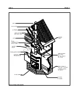
CHASE ENCLOSURE

If the chimney runs up the outside of the house, it must be
enclosed in a chase structure.  It is best to locate the chase
away  from  any  overhead  obstructions  and  meet  all  clear-

ances from such objects.  The chase should be construct-
ed  in  such  a  way  that  it  is  an  extension  of  the  home.  It
should be well insulated between the footings and the floor
of the home to prevent heat loss.  If the climate in your area
is mild, insulate the chase at least to the first firestop.  If the
climate in your area is very cold, insulate the chase to the
top  to  keep  the  flue  warmer,  to  increase  the  draft,  and
reduce creosote buildup. 

If required by local codes, make certain that the walls have
been properly insulated, vapour sealed and sheathed with
a fire rated gypsum board (see Figure 9-10).

Remember:  Check  local  codes  concerning  installation
requirements and restrictions in your area.

FIRE STOP

A fire  stop  must  be  placed  where  the  chimney  passes
through each floor level overhead.  This will assist in retard-
ing any spread of fire and act to contain the fire within the
area below the firestop.

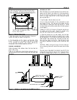
OFFSET CHIMNEY

• Maximum offset angle:  

45° 

• Maximum number of elbows:   four  (4),  resulting  in  two

(2) offsets.

Page 11

DELTA

10 feet min.

2 feet min.

storm collar

flashing &

radiation

shield*

12" min

insulation

chase liner of fire  rated
gypsum board is recom-
mended (may be required
by local authorities)

framing guide supplied

Delta

Figure 9 :  Chimney  installation with chase enclosure

2 feet

min.

10 feet min.

flashing &

radiation

shield*

12” min.

2” min.
clearance

Wall

support

Radiation
shield or
firestop

Insulated
angle (30ºor
45º radiation
shield)

Delta 

Figure 10: Offset chimney through a wall

*In USA: use vented flashing

In CANADA: use roof radiation

shield and regular 
flashing

storm collar

*In USA: use vented flashing

In CANADA: use roof radiation

shield and regular 
flashing

Summary of Contents for DELTA

Page 1: ...Keep these instructions for future use Owner s Manual Residential Factory Built Fireplace Operation Maintenance Installation Delta 01 03 The DELTA ...

Page 2: ...it 19 Remote Venting 19 The Gravity Vent System 21 The Central Heat System 24 Zone Heating WIRING DIAGRAMS 26 Zone Heat System 27 Thermostat 27 Circulating Blower 27 Central Heat System 27 All Systems Combined REPLACEMENT PARTS LIST 28 Replacement Parts List LABEL 29 Label WARRANTY 30 Warranty Page 2 Dear Customer The Delta incorporates technology with elegance to give you a beautiful view of the ...

Page 3: ... fire The chimney must be inspected periodically during the heating season to see if a creosote buildup has occurred If a significant layer of creosote has accumulated 1 4 or more it should be removed to reduce the risk of chimney fire Warning burn seasoned wood only Do not burn driftwood treated wood coal garbage plastic Do not use construction scraps e g 2x4 or plywood scraps as your only supply...

Page 4: ...it takes air from the room the Delta is in draws it around the fireplace and distributes it see Options Central Heating System parts FD HC6 FD HB6 NOTE The blower part FD HB6 can push warm air either up or down and can also be zone controlled see Options Zone Heating and diagrams HINT If some evening you would like to enjoy the ambi ence of the wood flame but you are a little too warm turn up the ...

Page 5: ...ver the pins can be turned so that the doors seal well and fit with each other After adjustment tighten the Allen screws holding the hinge pins in place with the screwdriver and replace the door If the left side door fits correctly and the front door does not pass the paper test then the angle bracket needs to be adjusted Loosen the four screws that are attached to the centre door and slightly adj...

Page 6: ...pipe This can be done by removing the cotter pin from the top right side of the secondary air pipe and sliding the pipe as far as it goes to the left Then when the right side drops out of its hole slide it to the right until the other side drops To remove the baffle push up and slide it off the brackets Replace both as you removed them and be sure the holes on the secondary air pipe are facing tow...

Page 7: ...onents for gravity system central heat blower framing guide standoff gravity vent damper handle Hearth extension radiation shield ceiling clearance 39 min 84 from base to the ceilling fresh air hood at floor level For other installation options see figure 7 electrical knockouts Figure 2 General assembly ...

Page 8: ...between the two forks before using STANDOFF INSTALLATION Before installing your Delta the side nailing strips need to be assembled as follows 1 Remove the nailing strips from the top of the unit 2 Remove the four 4 metal screws on each side of the Delta facing 3 Attach the nailing strip to the side of the Delta using the metal screws that you removed in Step 2 Figure 4 NOTE When using the optional...

Page 9: ...lexible pipe must be used 1 Use the side or back outside air outlet 2 Find a convenient location for the combustion air duct and intake air hood The location of the intake air hood may be above or below floor level see Figure 7 Under no circumstances should the combustion air inlet be placed in attic spaces 3 Make a 4 1 4 5 1 4 if using a 5 diameter duct hole in the outside wall of the house Mount...

Page 10: ...r above the radiation shield as shown in Figure 8 3 Place the first chimney length on the fireplace Secure the chimney length to the fireplace with the three screws provided The chimney must extend at least 3 ft above its point of contact with the roof and at least 2 ft higher than any wall roof or building within 10 ft of it Refer to the Excel instruc tion installation flue height requirements fo...

Page 11: ...heat loss If the climate in your area is mild insulate the chase at least to the first firestop If the climate in your area is very cold insulate the chase to the top to keep the flue warmer to increase the draft and reduce creosote buildup If required by local codes make certain that the walls have been properly insulated vapour sealed and sheathed with a fire rated gypsum board see Figure 9 10 R...

Page 12: ...must NOT go closer to the fireplace than the stand offs top back and sides You may also completely cover the top of the Delta as long as you main tain top standoff clearances and the 2 clearances around the chased chimney The 2 clearance around the chimney must be open to the fireplace up to the first fire stop 39 min SPARK GUARD Install a 5 piece of sheet metal centred under the joint between the...

Page 13: ...rk guard 16 min 8 min 44 Figure 16 Clearance to combustibles mantle is 50 1 2 mini mum from the base of the fireplace 10 1 2 min no limit to side surround as long as 11 side clearance is observed MANTEL A masonry or other non combustible mantle may be placed directly above the top louvers If a wood or other com bustible mantle is desired then it must be at least 10 1 2 inches above the top louver ...

Page 14: ...17 Installation of mantles and crown moulding backing 2x4 corner moulding hides mounting screws bolts screw bolt attaches crown moulding to backing 2x4 counter sink and fill crown moulding 11 6 12 25 4 12 24 47 12 12 8 6 16 2 5 5 35 3 29 19 44 2 framing guide 5 Figure 18 Unit dimensions 47 ...

Page 15: ...re will be some increase in warm air movement to the room serviced by the gravity vent If you desire even heat throughout your home strictly from your fireplace or if you want to move heat to a remote area of your home it is recommended that you incorpo rate the central heat option parts FD HC6 and FD HB6 A thermostatically controlled blower takes heat from the fireplace and distributes the warm a...

Page 16: ... blower with the outlet facing up from the back Fit the blower through the louver opening 3 Slide the blower into the two blower mounts being sure that it is pushed all the way down 4 Mount the thermo disc as shown in Figure 21 The front face of the fireplace is bent into a flange just above the lower opening The thermo disc mounts just above the centre louvers Push the clips on to the flange as f...

Page 17: ... it is recommended that you purchase the rock retainer kit part FD KD 1 to help keep the facing in place It is NOT recommended for brick or other self supporting materials Follow these steps NOTE Remove the fireplace doors and louvers and store them in a safe place until the masonry work is finished Acid from the cleaning operation will permanently damage the gold plating Ensure that the cover rem...

Page 18: ... must be removed for this option optional soldiering brick over louver openings Figure 25 Facing with soldiering brick Note when using a thicker facing be sure to leave enough room for the door to swing wide top framing guide use only the pre drilled holes in the rock retainer kit for screwing to the face spread plaster over more than a workable area so that the mortar will not set before the faci...

Page 19: ...rts is allowed These genuine RSF Woodburning Fireplaces parts have the correct clearances These clearances must be maintained for your safety exept that B vent components can be replace by ICC double wall black pipe ULTRABlack UBF use only UBF black pipe The FD VD system incorporates standard 8 B vent com ponents for installation Single wall pipe is not allowed due to the high temperature of the a...

Page 20: ...ur hand up inside and underneath bend up at least two of the four tabs at the base of the starter section to hold it in place 6 Install the shut off damper in the B vent starter sec tion through the left side louvers The shut off damper enables the manual control of hot air flowing through the gravity vent pipe With the top left louver removed and the angular portion of the rod in hand insert the ...

Page 21: ...be run at a 0 clear ance to combustibles Warning If you are ducting out of the top of the fireplace and the backdraft damper is not installed the central heat ducting will become too hot for the surrounding com bustible materials Any substitute for any RSF kit will void all liability and warranty coverage by RSF Woodburning Fireplaces Installation 1 Remove the cover to the left on the top of the D...

Page 22: ... ducting rigid or flex Any other size will not work properly Use only metal ducting between the fireplace and the blower You may use plastic ducting after the blower provided the temperature rating of the ducting is at least 250 F Do not use plastic ducting in a chase 7 To install the blower for the FD HB6 blower only attach the noise reduction collars to either side of the blower using 1 2 self t...

Page 23: ...is is the most pop ular use of the central heat blower Do not install it in the room where the fireplace is installed We recommend an electrician wire the following There are yellow black and red wires coming out of the relay as shown in the wiring diagram Connect the wire from 4 of the terminal block to the yellow relay wire and the black transformer wire with a wire marrette Connect the black re...

Page 24: ...ading if it is tested with a meter 2 If the blower still fails to operate consult your local RSF Woodburning Fireplaces authorized dealer for repair or replacement instructions ZONE HEATING FD HCZ 1 AND FD HCZ 2 For more regional heat control the Delta is ideally suited for zone heating Figure 38 shows an example of a three zone system The thermostat simultaneously opens the desired valve and star...

Page 25: ...heat plenum for circulation throughout all rooms example 2 tie in to part of the duct system Figure 36 examples of air circulation when tying in to existing ducting zone dampers zone thermostats Figure 37 Zone heating example of 3 zones ...

Page 26: ...ft damper motor internal blower thermal switch terminal block draft damper thermostat internal blower speed control black white black bare 110V relay yellow white black external blower control external central heat blower 24V 18ga LVT white Figure 38 Wiring for all systems with zone heat system zone thermostats heat only transformer ...

Page 27: ...iring for the central system 110V draft damper motor draft damper thermostat internal bower speed control blower control thermostat variable speed switch external central heat blower 110V black black black white yellow 1 2 internal blower thermal switch bare white white 18 ga LVT transformer Figure 42 Wiring for all systems combined For a warming thermostat 1 should be the red wire and 2 should be...

Page 28: ...31B 14 14 7 Thermostat RSF T822D2501 14 14 9 Controller 00100201 14 14 10 Control Centre 001 00204 14 14 11 Electric Blower Speed Control 5 14 14 13 Electric Blower c w Thermal Switch 11 1 D Refractory Back Right 11 2 D Refractory Back Left 11 3 D Refractory Side Right 11 4 D Refractory Side Left 11 5 D Refractory Bottom Right 11 6 D Refractory Bottom Left 11 7 D Refractory Front Right 11 8 D Refr...

Page 29: ... OPERATE ONLY WITH VIEWING DOOR CLOSED AND LATCHED OPEN TO FEED FIRE ONLY FOR USE WITH SOLID WOOD FUELS ONLY OPERATE ONLY WITH FIREBRICK IN PLACE WARNOCK HERSEY 00000 UN PLANCHER COMBUSTIBLE DOIT ÊTRE PROTÉGÉ PAR UN MATÉRIAU NON COMBUSTIBLE S ÉTENDANT AU MOINS 16 405 MM AU DEVANT ET 8 205MM SUR LES CÔTÉS DE L OUVERTURE DE LA PORTE DU FOYER PIÈCES REQUISES POUR L INSTALLATION TUYAU FLEXIBLE DE 4 ou...

Page 30: ... components Repairs or replacements necessitated by vandalism neglect abuse over firing improper fuel or fuel loads or failure to ade quately service the unit as stated in the owner s manual Repairs or replacements particularly charges for travel and labor not authorized by RSF Woodburning Fireplaces in advance LIMITATIONS All items found to be defective will be replaced or repaired upon return of...

Reviews: