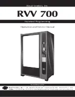
RVV 700 Standard Programming Service and Parts Manual
14
SECTION 2: Vender Component Explanation
Touch Pad
The 12-button touch pad is located on the right side of
the door front. The touch pad contains the numbers 0-9,
plus the * key and the # key. All programming and sales
selections are done by way of the touch pad.
Delivery Sensor
The delivery sensor actually consists of two separate
components which work in conjunction with one another.
The emitter, below the product delivery port, emits an
infrared beam. The receiver, above the delivery port,
receives the infrared beam. When a product falls into the
delivery port, the infrared beam is broken, signalling to the
VMC board that a vend has been made.
Door Switch
The door switch is mounted on the vender’s chassis above
the vender’s slide-out door. The door switch is actuated by
the door each time it is opened or closed. The following
functions are performed each time the vender door is
closed:
1. All sold-out selections are cleared;
2. The greeting scrolls on the display;
3. If door switch reset is enabled in programming, the
resettable MIS counters will be reset if at least one
selection has been read;
4. A 5-7 minute delay begins after which the refrigeration
unit will come on; and
5. The lighting system will turn on.
Liquid Crystal Display
(LCD)
The LCD is located above the validator. All information
to the programmer and to the customer is conveyed on the
LCD.
Power Module Assembly
The RVV 700 uses a power module assembly which
converts 115 volts AC (conventional voltage) to 24 and 36
volts DC, to power the vender’s control board. The power
module assembly is a major contributor to the vender’s
operation. Without it, the control board cannot function.
LOCATION OF ELECTRONIC POWER SUPPLY: The
power supply is located in the service section of the
vender. It is contained in a metal box which also holds
the master power switch and the fusebox assembly.
WARNING:
Before removing this box, remove power
from the vender by unplugging the main power cord from
the AC voltage source (wall outlet)!
Summary of Contents for RVV 700
Page 4: ...RVV 700 Standard Programming Service and Parts Manual 4 TABLE OF CONTENTS continued...
Page 42: ...RVV 700 Standard Programming Service and Parts Manual 42 SECTION 5 Troubleshooting...
Page 43: ...43 RVV 700 Standard Programming Service and Parts Manual SECTION 5 Troubleshooting...
Page 74: ...RVV 700 Standard Programming Service and Parts Manual 74 Wiring Schematic...
Page 75: ...75 RVV 700 Standard Programming Service and Parts Manual Wiring Schematic...


