background image

18 


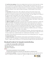
enough pressure to compensate for the pressure drop from feed to concentrate.  The pressure should 
be low enough so that little to no permeate is produced.  A low pressure minimizes re-deposition of 
dirt on the membrane.  Dump the concentrate, as necessary, to prevent dilution of the cleaning 
solution. 
3.


Re-circulate.  After the process water is displaced, cleaning solution will be present in the 

concentrate stream that can be recycled to the cleaning solution tank.  Recycle the cleaning solution 
for 10 minutes or until there is no visible colour change.  If at any time during the circulation process 
there is a change in pH or a colour change, dispose of the solution and prepare a new solution as 
described in step 2.  A pH of 2 must be maintained for the cleaning to be effective. 
4.


Soak.  Turn the pump off and allow the elements to soak.  Soak the elements for 1-15 hours 

(soaking overnight will give best results).  To maintain temperature during an extended soak period, 
use a slow recirculation rate (2-5 litres per minute).  Soak time will vary depending on the severity of 
the scaling.  For lightly scaled systems, a soak time of 1-2 hours is sufficient. 
5.


High-flow pumping.  Feed the cleaning solution at 15-20 litres per minute for 45 minutes.  The 

high flow rate flushes out the foulants removed from the membrane surface by the cleaning.  If the 
elements are heavily fouled, using a higher flow rate is possible up to the maximum pressure drop 
across the membrane permissible (check with membrane manufacturer’s data sheets).  With higher 
flow rates, excessive pressure drop may be a problem.  The maximum recommended pressure drops 
for most common membranes are 100kPa per element or 340 kPa per multi-element vessel, whichever 
value is more limiting. 
6.


Flush out.  Clean RO permeate water is preferred for this stage.  If clean RO permeate water is not 

available, pre-filtered raw water can be used for flushing out the cleaning solution unless there will be 
corrosion problems (e.g., stagnant seawater will corrode stainless steel piping).  To prevent 
precipitation of any remaining contaminants, the minimum flush out temperature is 20°C.  The system 
should be flushed for 1 hour 
7.


Re-start the system.  The RO elements and the system need to stabilize before taking any 

performance data. The stabilization or normalisation period will vary depending on the severity of the 
fouling.  To regain optimum performance, it may take several cleaning and soak cycles. 


Additional Information 

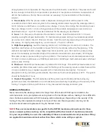
Never recirculate the cleaning solution for longer than 20 minutes. With longer recirculation, the 

carbonate scale can re-precipitate and end up back on the membrane surface, making it more difficult to 
clean. Carbonate scale reacts with HCl releasing carbon dioxide gas. Depending on the severity of the 
fouling, it may take repeated cleanings to remove all the scale. Cleaning severe scale may not be 
economical and element replacement may be the best choice. 


NOTE! 

These recommendations are specific for the ROTEK membrane elements used in these 

reverse osmosis systems and may not be compatible with other brands of membrane elements.   
It is your responsibility to ensure the suitability of these recommendations and procedures if they 
are applied to membrane elements other than those which come with your system.


Summary of Contents for KSRO Series

Page 1: ...KSRO Series Reverse Osmosis System Installation Manual...

Page 2: ...esigned with a fixed recovery rate of 60 65 by using ROTEK extra large flow RO membranes that can produce 4000 6000GPD 650 1000LPH of permeate water flow which means it can produce more pure water at...

Page 3: ...aw requires it or you prefer to we recommend using a professionally licensed installer or plumber who meets the requirements of this system All O Rings fittings filter canisters and Teflon tape wear o...

Page 4: ......

Page 5: ...Components List 5 System Overview 6 System Guide 7 Installation Procedure 8 System Startup Operation 10 C5TM RO Controller 11 Flow Meter and Pressure Gauges 13 Troubleshooting 13 System Maintenance 14...

Page 6: ......

Page 7: ...om for filter replacements System Specifications KSRO system recovery rate is calculated based on the volume of flush water discharged Recovery Rate Permeate Flow Permeate Flow Discharged Flush Flow P...

Page 8: ...olids 1000 ppm Organics 1 ppm Turbidity SDI 5 Temperature 5 to 40 C pH 3 11 Silica 1 0 ppm Iron 0 01 ppm Pressure 240 kPa These specifications should be met in order to have the reverse osmosis system...

Page 9: ...using ROTEK s existing standard pretreatment module of course it can also be customized according to your raw water conditions KSRO Pretreatment Unit Optional 1 20 filter housing x 1pcs 5 m GAC filte...

Page 10: ...Ensure that power lead is rated to carry the current draw of the system A minimum electrical wire diameter of 3 5mm is recommended 3 The external storage tank level contact switch should be connected...

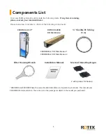
Page 11: ...O Main Unit ROTEK XL 4040 RO Membrane Flexible PE Tubing 5 m Filter Housing Wrench Installation Manual Solenoid Valve Diaphragm KSRO4000 and KSRO6000 have the same standard installation and operation...

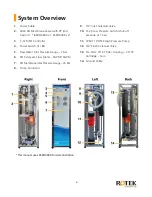
Page 12: ...e Gauge 7 Bar 6 RO Permeate Flow Meter 5GPM 10GPM 7 RO Membrane Inlet Pressure Gauge 35 Bar 8 Pump Contactor 9 3 4 Inlet Solenoid Valve 10 LF 20 Low Pressure Switch shut off pressure at 1 bar 11 LPE2...

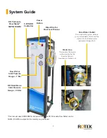
Page 13: ...the impure water rejected by the Reverse Osmosis membrane is flushed out This manual uses KSRO4000 for demonstration The RO Permeate Flow Meter can be 5GPM 10GPM is subject to the model you purchased...

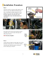
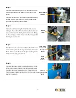
Page 14: ...on the label should head downward Place back the PP end cap of the membrane vessel and Make sure to lock the water outlet pipe and safety ring are secure NOTE Do not overtighten Step 2 Connect the pre...

Page 15: ...he sink pipe a floor drain or another design that discharges wastewater Step 5 Take the blue wire and connect this to the float level sensor in the permeate storage tank This allows the RO to turn on...

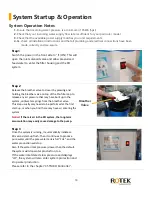
Page 16: ...alve on top of the Pre filter cap to release any air pressure that may have built up in the system until water springs from the breather valve This step usually only needs to be performed at the first...

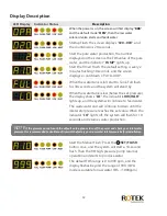
Page 17: ...RO system will stop making water and stand by Flush Green The system is running an automatic flush cycle of the RO membrane Pump Green The RO high pressure pump is running and making water Low Red Th...

Page 18: ...nk is low below the set pressure the display shows LO the indicator LOW INLET lights up and the system will continue to feed water The wastewater end will continue to drain until the inlet water press...

Page 19: ...se use the water supply storage tank and booster pump to supply water to the RO system and prevent the system from circulating Why is the output of my RO pure water getting less 1 If the output of RO...

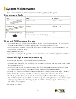
Page 20: ...e chapter Vacation Mode How to Change the Pre filter Housing Recommended about every 3 months depending on water use 1 You will need a clean cloth dish soap and 20 PP Cartridge 5um filter The system m...

Page 21: ...the new 4040 RO Membrane and insert the new RO Membrane in the Membrane Housing in the correct direction you noted earlier 4 Make sure to push the Membrane in firmly then close the vessel by tightenin...

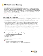
Page 22: ...solved and well mixed before circulating the solutions through the membrane elements 2 It is recommended the membrane elements be flushed with good quality chlorine free water after cleaning Permeate...

Page 23: ...g If the elements are heavily fouled using a higher flow rate is possible up to the maximum pressure drop across the membrane permissible check with membrane manufacturer s data sheets With higher flo...

Page 24: ...tes excessive pressure drop may be a problem The maximum recommended pressure drops for most common membranes are 100kPa per element or 340 kPa per multi element vessel whichever value is more limitin...

Page 25: ...age and power supply What is the discharge rate The typical discharge rate range of KSRO is 1 2 gallon for every one gallon produced Your water pressure incoming water quality and water temperature wi...

Page 26: ...ertically on a clean surface until dry 3 Place each filter individually in a sealed air tight plastic wrap and place in the refrigerator for the duration if filter is reusable and less than 3 months o...

Page 27: ...ime Covered This warranty is effective for 1 full year from the date of the original purchase Not Covered This warranty does not cover labor for removal or installation accumulation of dirt or grime y...

Page 28: ...e operating hours Water inlet pressure kPa 140 650 kPa Membrane inlet pressure kPa 700 1400 Pure water flow rate lpm 3 5lpm Membrane Feed Water Conductivity or TDS Pure Water Conductivity or TDS Salt...

Reviews: