


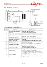

Controller functions
UPT-606
Page 39
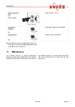
9.11
Diagnostic interface/visualization
software
(as of software revision 100)
An interface with a 6-pole Western socket is provided
for systemdiagnostics and process visualization. This
interface allows a data connection to be set up to the
ROPEX visualization software using the ROPEX com-
munication interface CI-USB-1.
Only a ROPEX comunication interface is
allowed to be connected to the diagnostic
interface. Connecting another device (e.g. a tele-
phone cable) could result in malfunctions or
damage to the controller.
The ROPEX visualization software is described in a
separate document.
9.12
System monitoring/alarm output
To increase operating safety and to avoid faulty heatse-
aling, this controller incorporates special hardware and
software features that facilitate selective fault detection
and diagnosis. Both the external wiring and the internal
system are monitored.
These features assist the operator in identifying the
cause of abnormal operations.
A system fault is reported or differentiated by means of
the following indications.
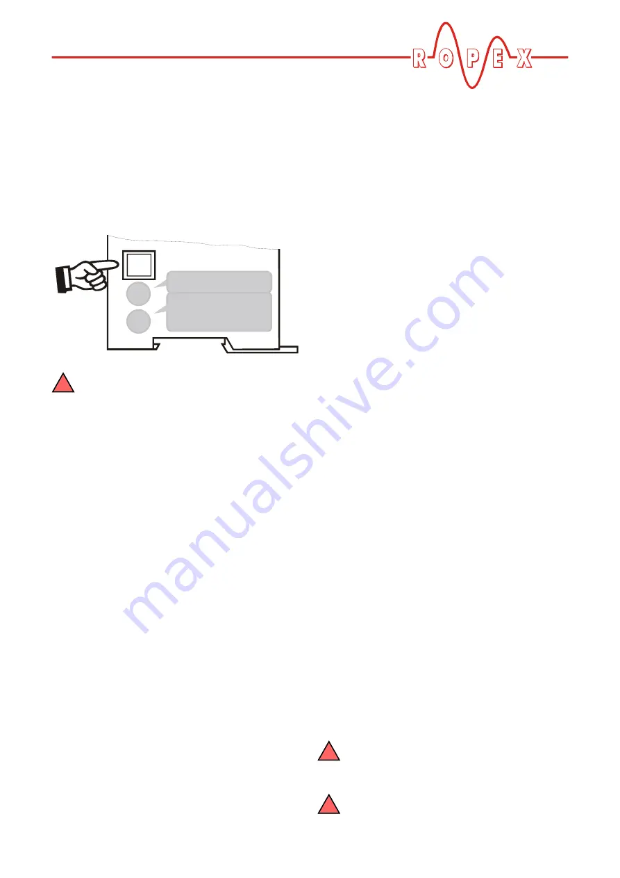
A.)
Red "ALARM" LED on the controller with
three states:
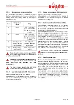
1.
Blinks fast (4Hz)
The AUTOCAL function should be executed (error
codes 8+9).
2.
Blinks slowly (1Hz)
The system configuration is incorrect and the zero
calibration (AUTOCAL function) was unsuccessful
(
section 8.2 "Controller configuration" on
page 16). It corresponds to error codes 10…12.
3.
Lit continuously:
This indicates that a fault is preventing the controller
from being started (error codes 1…7).
As a rule, it refers to an external wiring fault.
B.)
Alarm relay (relay contact terminals
12+13+14):
This relay is set in the factory as follows:
•
DE-ENERGIZED
in operating states A.1 and A.2,
but energized if the "ST" bit is activated in one of
these states.
•
ENERGIZED
in operating state A.3.
If the alarm relay is configured opposite to the factory
setting (
section 8.2.4 "Configuration of the alarm
relay" on page 18), these states are reversed.
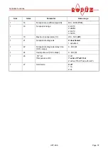
C.)
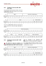
Error code indication via the PROFIBUS
protocol
If a fault occures the "AL" bit is set and in the compact
protocol the alarm code appears instead of the actual
value in bits 0…3, while in the extended protocol it is
contained at bit positions 8…11 in the second word
(
section 9.6.9 "Error codes" on page 29).
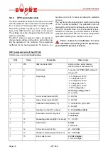
D.)
Error code output via the 0
…
10VDC analog
output (terminals 17+18):
Since a temperature indication is no longer necessary
if a fault occurs, the analog output is used to display
error messages in the event of an alarm.
12 voltage levels are offered for this purpose in the
0…10VDC range, each of which is assigned an error
code (
section 9.13 "Error messages" on page 40).
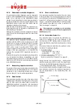
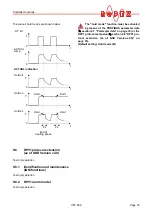
If a state that requires AUTOCAL occurs – or if the con-
troller configuration is not correct – (error codes 8…12),
the signal at the analog output jumps back and forth at
1Hz between the voltage value which corresponds to
this error and the end of the scale (10VDC, i.e. 300°C).
If the "ST" bit is activated in one of these states, the
voltage value does not change any more.
Selective fault detection and indication can thus be
implemented simply and inexpensively using the
analog input of a PLC with a corresponding error mes-
sage (
section 9.13 "Error messages" on page 40).
An alarm can only be reset by activating the
„RS“ bit or by switching the controller off and
then on again.
If an error message is reset using the "RS"
bit, the "RS" bit must be deactivated first.
0
5
1 2
3
4
6
7
8
9
DI
A
G
!
!
!