


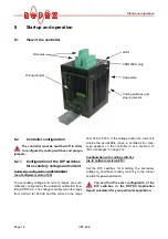


Startup and operation
UPT-606
Page 19
The base resistance of the heating elements
rises continuously during operation (con-
struction-conditioned). Due to this the AUTOCAL
function must be executed every 100.000 sealing
cyles for preventing measurement failures of the
ACTUAL temperature.
8.3.2
Replacing the heating element
All power supply leads must be disconnected from the
CIRUS temperature controller in order to replace the
heating element.
The heating element must be replaced in
accordance with the instructions provided by
the manufacturer.
Each time the heating element is replaced, the zero
point must be calibrated with the AUTOCAL function
(
section 9.5.1 "Automatic zero calibration
"AUTOCAL" (AC)" on page 26) while the element band
is still cold. The correction factor Co (
section 9.7.10
"Correction factor Co" on page 32) must be adjusted
too. With this procedure the production-related resis-
tance tolerances of the heating element will be com-
pensated.
8.4
Startup procedure
Please also refer to section 1 "Safety and warning
notes" on page 3 and section 2 "Application" on
page 4.
Installation and startup may only be per-
formed by technically trained, skilled per-
sons who are familiar with the associated risks and
warranty provisions.
8.4.1
Initial startup
Prerequisites: The controller must be correctly installed
and connected (
section 7 "Installation" on page 10).
Proceed as follows to start up the controller for the first
time:
1. Switch off the line voltage and verify that all circuits
are de-energized.
2. The supply voltage specified on the nameplate of
the controller must be identical to the line voltage
that is present in the plant or machine. The line fre-
quency is automatically detected by the tempera-
ture controller in the range from 47…63Hz.
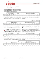
3. In case of controllers up to software revision 015,
the settings of the DIP switches on the controller are
indicated in the ROPEX Application Report and
depend on the heating element that is used.
The settings of the coding switches on the controller
depend on the required station address in the PRO-
FIBUS network (
section 8.2 "Controller configu-
ration" on page 16).
4. Link the device master file into the PROFIBUS
master (
section 9.3), select the required commu-
nication module ("compact" or "extended" protocol)
and start the communication.
5. Make sure that the "ST" bit is not set.
6. Switch on the line voltage and the 24VDC auxiliary
supply (the order is arbitrary).
7. When the voltage is switched on, the yellow
"AUTOCAL" LED lights up for approximately
0.3seconds to indicate that the controller is being
powered up correctly. This LED blinks slowly (1Hz)
as long as no PROFIBUS communication is active.
It does not go out again until it detects an active
communication.
As of software revision 100:
If the red "ALARM" LED lights up for 0.3s in
addition to the yellow "AUTOCAL" LED when the
voltage is switched on, the configuration of this
controller has been changed in the visualization
software (
section 9.11 "Diagnostic interface/
visualization software (as of software
revision 100)" on page 39). In order to avoid mal-
functions, please check the controller configura-
tion before continuing the startup procedure.
8. The green "DATA EXCHANGE" LED lights up to
indicate an active PROFIBUS communication.
!
!
!
!