


Controller functions
UPT-606
Page 29
For controllers with software revision 100, 101 and 102
the configuration for the „TO“ bit can be set via the
ROPEX visualization software. As of software revision
103 the configuration for the „TO“ bit is set in the PRO-
FIBUS parameter data (or the DPV1 protocol exten-
sion). A configuration with the ROPEX visualization
software is no more possible.
9.6.6
Controller active (RA)
The UPT-606 has processed the "START" request suc-
cessfully and entered the control mode if the "RA"
bit = 1.
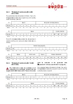
9.6.7
Sign (VZ)
In the compact protocol, the sign bit indicates whether
the actual value is positive or negative.
9.6.8
Actual value
If you are using the
compact
protocol, the actual value
itself is always positive. The sign bit (VZ) then indicates
whether the amount of the actual value is positive or
negative. If an alarm is signaled, the actual value con-
tains the error code.
If you are using the
extended
protocol, all 16 bits of the
first word must be interpreted as a signed number (twos
complement notation). During the calibration procedure
or if an alarm is signaled, the actual value is 0. The error
code is contained in separate bits.
9.6.9
Error codes
If a fault is signaled („AL“ bit = 1), the error code allows
the exact cause to be determined. The "Error code
format" parameter determines whether two or three-
digit error codes are output. If two-digit error codes are
specified, some faults are grouped together; three-digit
error codes enable a fault to be identified more preci-
sely.
In the compact protocol, the error code appears instead
of the actual value in bits 0…3 (error code format = 4-
bit) or 0…9 (error code format = 10-bit).
In the extended protocol, the error code appears in the
second word at bit positions 8…11 (error code
format = 4-bit) or 6…15 (error code format = 10-bit)
(
section 9.13 "Error messages" on page 40).
10-bit error codes are available on all control-
lers as of software revision 100 and supplied
with GSD Version v2.0. Older controllers only show
4-bit error codes.
In addition to the error codes, the PROFIBUS diagno-
stics function also sends error messages to the PRO-
FIBUS master. The error messages corresponding to
each error code are already stored in the device master
file (GSD), so that they automatically appear in plain
text on the PROFIBUS master whenever the device
diagnosis for the UPT-606 is interrogated there. The
language in which the error messages are displayed
depends on the selected device master file.
The PROFIBUS diagnostics function always
transfers 4-bit error codes regardless of the
setting of the "Error code format" parameter
(
section 9.7.9 "Error code format" on page 32).
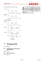
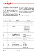
Set
Set+
Δϑ
lower
Set+
Δϑ
upper
Actual value
Time
Time
0
1
„ST“ bit
Time
0
1
„TO“ bit
a.) Temperature
not
OK
Set
Set+
Δϑ
lower
Set+
Δϑ
upper
Actual value
Time
Time
0
1
„ST“ bit
Time
0
1
„TO“ bit
b.) Temperature OK
!
!