


Controller functions
Page 32
UPT-606
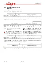
9.7.6
Extended controller diagnosis
The extended controller diagnosis uses the diagnostic
function of the PROFIBUS protocol to display several
faults of the UPT-606 on the PROFIBUS master
directly. For each fault there is a text message stored in
the device master file so the error codes appear on the
PROFIBUS master in plain text if the master has the
capability to display text messages.
With the help of parameter No. 9 the extended con-
troller diagnosis can be activated or deactivated. The
default setting is "activated".
Although the extended controller diagnosis ist deacti-
vated, there is the fault diagnosis which is coded in the
protocol.
DPV1 protocol extension (alarm model):
The extended device diagnostic functionality is not
available with the DPV1 protocol extension and GSD
Version v2.0 or higher (
section 9.8 "DPV1 protocol
extension (as of GSD Version v2.0)" on page 35. The
DPV1 alarm model (
section 9.8.2 "DPV1 alarm
model" on page 35) must be used in this configuration
instead. In this case, parameter no. 9 in the GSD file
switches the so-called DPV1 diagnostic interrupt on
and off.
If you want to keep the old extended device diagnostics
(e.g. for reasons of software compatibility), you must
use a GSD version previous to v2.0. The DPV1 functio-
nality for the UPT-606 is then automatically deactivated
in the PROFIBUS master.
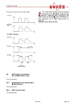
9.7.7
Measuring impulse duration
The length of the measuring impulses generated by the
controller can be set with parameter no. 10. It may be
necessary to set a measuring impulse that is longer
than the default 1.7ms for certain applications.
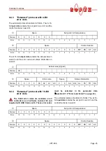
9.7.8
Data format
This parameter specifies the order of the bytes (Intel:
"high/low byte", Motorola: "low/high byte") in the cyclic
data for both input and output data (
section 9.4
"PROFIBUS protocol" on page 23). We recommend
setting "low/high byte (Motorola)" for Siemens control-
lers.
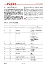
9.7.9
Error code format
This parameter specifies the length of the error codes
in the cyclic data. You can choose between a 4-bit and
a 10-bit format (
section 9.4 "PROFIBUS protocol" on
page 23). "4-bit" generates two-digit error codes in the
range 1…3 and is the default setting. "10-bit" generates
more detailed three-digit error codes (
section 9.13
"Error messages" on page 40).
This parameter is available on all controllers
a of software revision 100and supplied with
GSD Version v1.6.
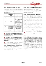
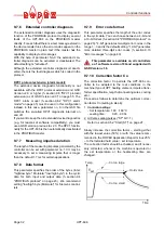
9.7.10 Correction factor Co
The correction factor Co permits the UPT-606 con-
troller to be adapted to the real conditions in the
machine (type of UPT heating element, impulse trans-
former specification, length of connecting wires, cooling
etc.).
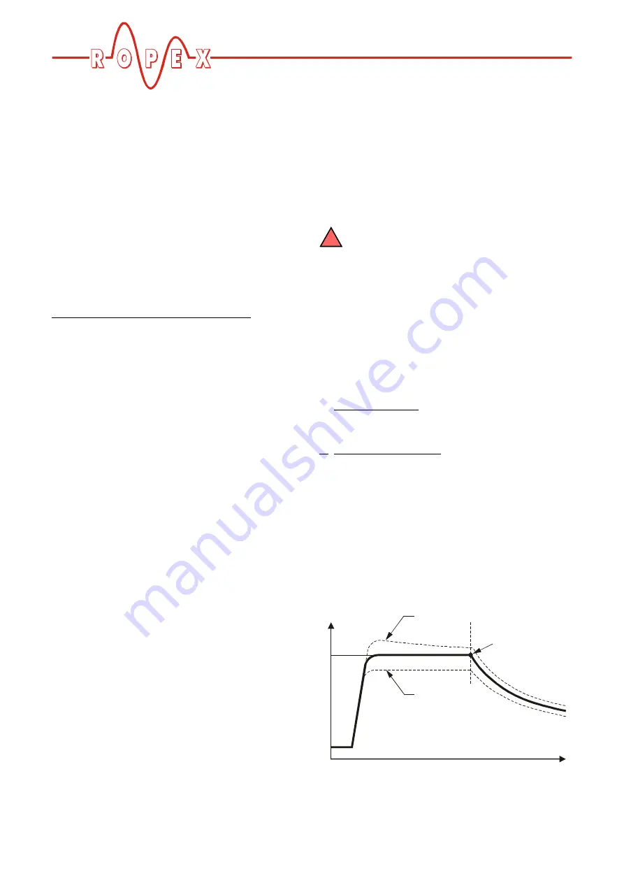
Proceed as follows to determine the optimum correc-
tion factor Co (setting in step 6):
1. Controller settings:
- Set temperature: 160…180°C
- sealing time:
0.20…0.30s
2. Activate sealing pulses ("ST" bit = 1)
Refer to section 9.5.2 "Start (ST)" on page 27.
Slowly increase the correction factor – starting either
with the lowest value (50%) or with the value recom-
mended in the ROPEX Application Report minus 25%
– to the indicated hold value = set temperature.
The correction factor should be checked, and if neces-
sary corrected, whenever the machine is operated or
the set temperature or the heatsealing time are
changed.
!
Temp.
Time
x
x
Hold value
Co too large
Co too small
T
set