
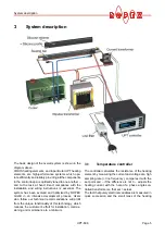
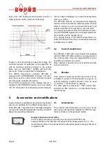


Dimensions
Page 10
UPT-606
6
Dimensions
7
Installation
See also section 1 "Safety and warning notes" on
page 3.
Installation and startup may only be per-
formed by technically trained, skilled per-
sons who are familiar with the associated risks and
warranty provisions.
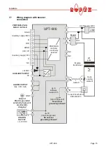
7.1
Installation steps
1. Please refer to the safety and warning notes
(
section 1 "Safety and warning notes" on page 3).
2. The information provided in the customized ROPEX
Application Report, which is prepared by ROPEX
specifically for each application, should be heeded
at all times.
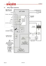
3. All electrical components, such as the controller, the
impulse transformer and the line filter, should be
installed as close as possible to the UPT sealing
bar(s) in order to avoid long wires.
4. Connect the voltage measurement cable U
R
directly
to the UPT sealing bar and lay it twisted to the con-
troller (UML-1 voltage measurement cable
section 4 "Accessories and modifications" on
page 6).
5. Ensure an adequate cable cross-section for the pri-
mary and secondary circuits (
Application Report).
6. Use only ROPEX impulse transformers or transfor-
mers approved by ROPEX. Please note the power,
the duty cycle and the primary and secondary
voltages (
Application Report).
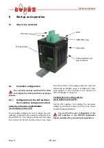
7.2
Installation procedure
Proceed as follows to install the CIRUS temperature
controller UPT-606:
1. Switch off the line voltage and verify that the circuit
is de-energized.
2. The supply voltage specified on the nameplate of
the CIRUS temperature controller must be identical
to the line voltage that is present in the plant or
machine. The line frequency is automatically
detected by the CIRUS temperature controller in the
range from 47Hz...63Hz.
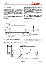
3. Install the CIRUS temperature controller in the elec-
trical cabinet on a standard top hat rail (DIN TS35
rail, according to DIN EN 50022). If several control-
75.0
90.0
11
3
.0
13
5.
0
!