


Controller functions
UPT-606
Page 23
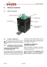
9.2
PROFIBUS communication „up to
SW-Rev 015“/“as of SW-Rev 100“
On controllers up to software revision 015, PROFIBUS
communication is only assured if the 24VDC power
supply (terminals 5+7 and PROFIBUS connector pins
7+2) and the line voltage are present. If the line voltage
is switched off (e.g. for safety reasons in order to open
a door), the PROFIBUS master indicates a bus fault
because PROFIBUS communication is not possible on
the RES-406.
This problem has been rectified on controllers as of
software revision 100. PROFIBUS communication is
always possible on these controllers as long as the
24VDC power supply is present, i.e. switching off the
line voltage no longer results in a bus fault.
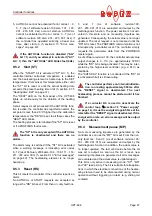
If the line voltage is not present however (e.g.
if it is switched off in order to open a door),
error code 901 (error group 7, no line voltage/sync
signal) appears on controllers manufactured as of
software revision 100 and the alarm relay is swit-
ched. This error can be reset by switching on the
line voltage again and activating the "RS" bit
(
section 9.5.3 "Reset (RS)" on page 27).
The error code that appears if the line voltage is swit-
ched off can be easily processed, and switching of the
alarm relay suppressed, in the PLC program.
If controllers as of software revision 100 are
installed in an older machine (e.g. in order to
carry out repairs), this new controller function can
lead to unwanted error codes when the line voltage
is switched off, depending on the PLC program.
Permanently disconnecting the 24VDC power
supply (terminals 5+7 and PROFIBUS connector
pins 7+2) results in the same behavior as on older
controllers (up to software revision 015), i.e. a bus
fault in the PROFIBUS master.
9.3
Device master file (GSD)
Configuring tools for the PROFIBUS-DP master that
must be configured interpret the contents of the slave
device master files and use them to create a master
parameter set for the PROFIBUS master, which is
responsible for useful data communication. The
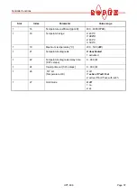
ROxy07EA.GSD
file (
xy
: GSD Version; e.g „15“ for ver-
sion „v1.5“) of the UPT-606 contains all the controller
information needed for the configuration, e.g. the pos-
sible baud rates, parameter descriptions, error mes-
sages etc. The device master files and the associated
display files (.DIB, for visualizing states) are supplied
with the controller in German (.GSG) and English
(.GSD or .GSE) on a diskette. They can also be reque-
sted by E-Mail (
) or they can be
downloaded from our Homepage (
www.ropex.de
).
After the required device master file has been linked
into the configuring tool, you must select one of the two
communication modules ("compact" or "extended").
This determines which protocol will be used by the
UPT-606 to communicate with the PROFIBUS master.
If you want to use all features of the controller
make sure that the appropriate version of the
device master file is used.
9.4
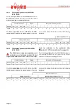
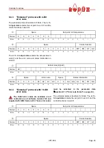
PROFIBUS protocol
The PROFIBUS protocol can be configured either as
"compact" (16bits for input data and 16bits for output
data) or as "extended" (2x16bits for input data and
2x16bits for output data). The protocol is determined at
the configuring stage by selecting a module ("compact"
or "extended"). The compact protocol is sufficient for
efficient communication with the UPT-606. The
extended protocol separates the set point and the
actual value of the UPT-606 from the status information
and the control functions, to enable it to be decoded
more easily by the PROFIBUS master.
Bits 0…7 form the low byte and bits 8…15 the
high byte ("INTEL format").
!
!
!
required GSD version
!