


Controller functions
Page 26
UPT-606
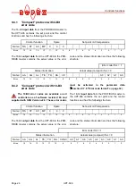
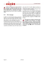
The 2x16-bit
output data
contains the actual value in
word
and the error code and status information in
word
:
9.5
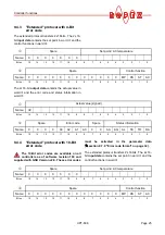
Input data
The term "input data" refers to the data that is trans-
ferred from the PROFIBUS master to the UPT-606. It
contains the set point and the control functions, such as
START or AUTOCAL for the UPT-606. These functions
are explained in the following.
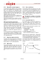
9.5.1
Automatic zero calibration
"AUTOCAL" (AC)
Because of the automatic zero calibration (AUTOCAL)
function, there is no need to adjust the zero point manu-
ally on the controller. This function matches the con-
troller to the resistance of the system and calibrates it
to the value which is predefined in the parameter data
(section 9.7.4 "Variable calibration temperature" on
page 31). If no parameter data is transferred by the
PROFIBUS master, the default value is 20°C.
Some PROFIBUS masters do not allow the parameter
data to be changed during operation. It is therefore not
possible to adapt the calibration temperature to the pre-
vailing ambient conditions in the machine.
As of software revision 100 and supplied with GSD Ver-
sion v2.0, the calibration temperature can be specified
by means of the "Set point/AC temperature" input data
whenever the zero point is calibrated, providing this
setting is selected in the parameter data
(
section 9.7.4 "Variable calibration temperature" on
page 31). It can be specified in the 0…+40°C range.
The value selected for the calibration temperature must
be entered in the "Set point/AC temperature" input data
when the "AUTOCAL" function is activated
("AC" bit = 1). If the specified temperature is too high
(greater than 40°C) or if the selected value varies, an
error message appears (error codes 115 and 116;
section 9.13 "Error messages" on page 40).
The AUTOCAL request ("AC" bit = 1) is executed by
the controller providing the AUTOCAL function is not
disabled.
The automatic calibration process takes about 10…15
seconds. The heatsealing element is not heated during
this process. The yellow LED on the front panel lights
up while the AUTOCAL function is active and the con-
troller reports "AUTOCAL active" ("AA" bit = 1) in the
output data. The actual value output (terminals 17+18)
is 0…3°C (corresponds to app. 0 VDC).
If the temperature of the heatsealing element varies on
controllers as of software revision 100, the "AUTOCAL"
function is executed a maximum of three times. If the
function still cannot be terminated successfully, an
error message appears (
section 9.13 "Error mes-
sages" on page 40).
You should always wait for the heatsealing
element to cool down (to ambient tempera-
ture) before activating the AUTOCAL function.
Reasons for disabled AUTOCAL function:
1. The AUTOCAL function cannot be activated until
10 seconds after the controller is switched on.
During this time the controller reports "AUTOCAL
disabled" ("AG" bit = 1) in the output data.
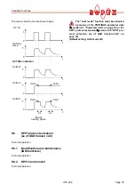
2. The AUTOCAL function is not activated if the heat-
sealing element is cooling down at a rate of more
than 0.1K/sec. If the "AC" bit is activated, the func-
tion is executed automatically providing the cooling
rate has fallen below the above-mentioned value.
3. If the "START" bit ("ST" bit = 1) is activated, the
AUTOCAL function is not executed ("HEAT" LED
lit).
4. If the "RESET" bit ("RS" bit = 1) is activated, the
AUTOCAL function is not executed.
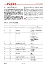
Actual value (signed)
Name:
VZ
Bit no.:
15
14
13
12
11
10
9
8
7
6
5
4
3
2
1
0
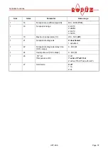
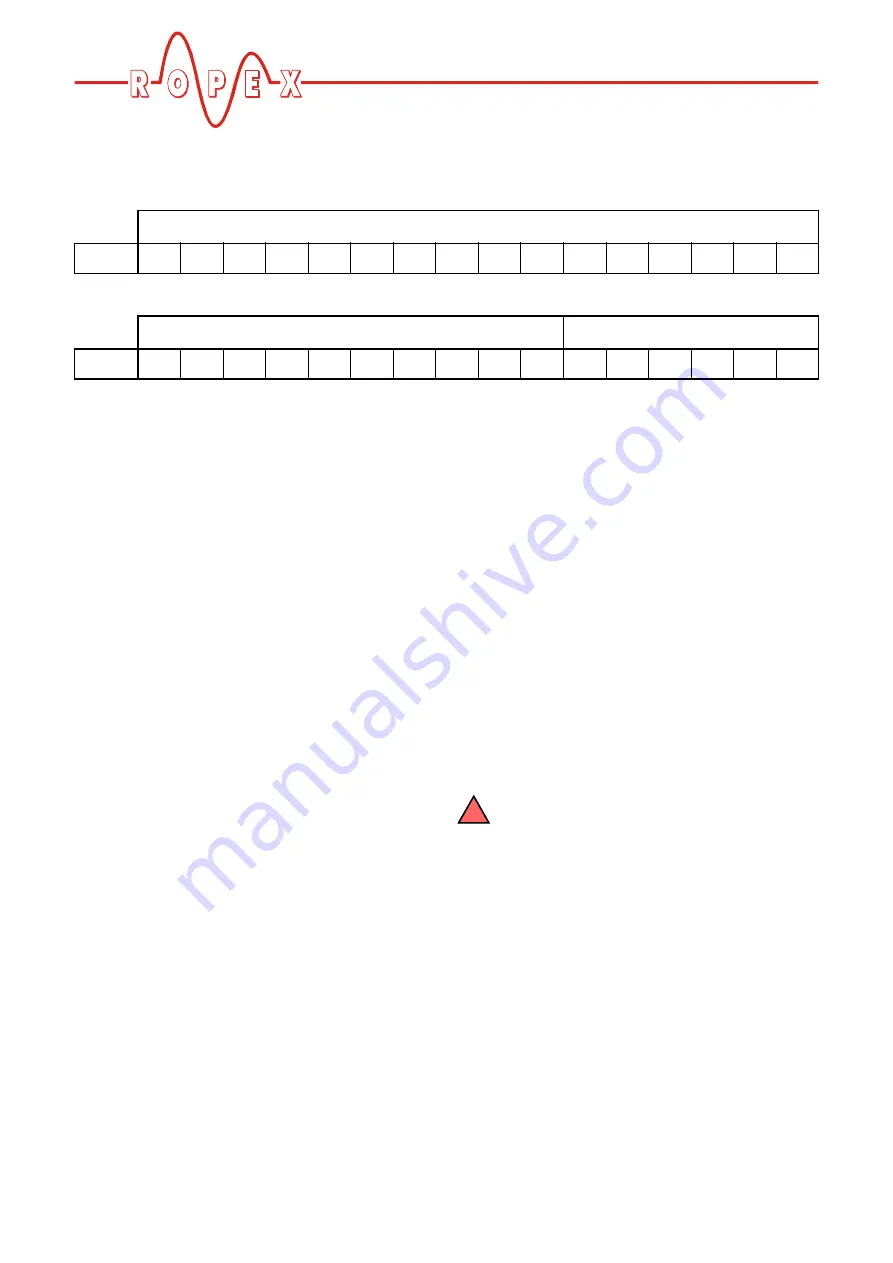
Error code
Status information
Name:
A9
A8
A7
A6
A5
A4
A3
A2
A1
A0
AA
AG
AL
TE
TO
RA
Bit no.:
15
14
13
12
11
10
9
8
7
6
5
4
3
2
1
0
!