


Rockwell Automation Publication 7000L-UM301F-EN-P - March 2020
237
Commissioning
Chapter 4
Press the start button and the drive should start running, pumping 0.1 pu (10%)
of rated current through the DC link. Alpha Rectifier should be approximately
90…92°.
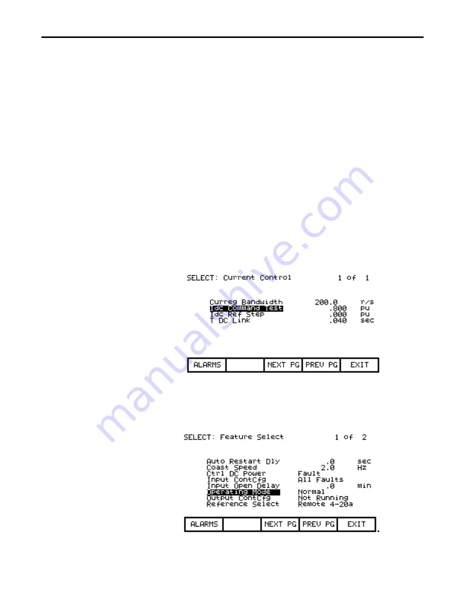
We can also check the Idc Reference and Idc Feedback on this same screen. Idc
reference should be at 0.100 pu and Idc Feedback should be around that same
number. Ensure that Idc error stays around 0.
The Idc waveform can be observed from T21 (Idc1) on the ACB board. The test
point should show 6 ripples per cycle for a 6-pulse drive. The waveform should
have an offset of 0.5V for each 0.1pu of Idc Test Command. The waveform
should also never have any of the low points between ripples go to 0V. This
would indicate a problem with the DC Link cabling. See the troubleshooting
section for sample waveforms.
Press MODIFY [F7], and increase Idc to .2 pu, and repeat the process. Go as high
as 0.7 pu in 0.1p.u steps for 18 Pulse, and 0.3 pu in 0.1pu steps for AFE, verifying
each level as you increase the current. For AFER, the Idc test is limited to 0.3 Idc
reference. If there is a current meter somewhere on the input to the transformer/
drive, check the current to ensure that it matches up with what you think we are
pumping.
When we are satisfied everything is OK, bring the IDC current down in steps of
.1 pu to 0, and then stop the drive. Return to the Feature Select parameter group
and change Operating Mode back to Normal.


