


12
Assembly
Operating manual neoTower® Premium L / 03.2017
4.
Assembly
4.1
Safety instructions for assembly
D
WARNING!
Hazard caused by failing to observe the assembly
instructions.
Errors made when installing the system can cause serious
injuries or material damage to the system or the building.
This chapter contains important information regarding the
safe assembly of the system.
A
Read this chapter carefully before assembling the
system.
A
Follow the safety instructions.
A
Carry out the assembly as described.
The assembly must only be performed by trained
personnel.
Electrical work must only be performed by qualified,
skilled electricians.
D
“2.2.3 Trained personnel” (page 6).
B
The system must be undamaged and in a faultless
condition before assembly.
B
Only use suitable fittings.
B
Cables and lines must not be damaged, kinked or
crimped.
B
Before assembling, ensure that the supply voltage has
been and remains disconnected.
The supply voltage is only reconnected when instructed
in the respective assembly step.
B
The generation unit must be transported to
the installation location by means of a suitable
transportation device (e.g. lift truck).
If it is not possible to transport it to the installation
location (e.g. lack of space):
A
Contact the manufacturer.
4.2
Installation location requirements
D
WARNING!
Risk of suffocation, gas explosions or material damage
caused by incorrectly installing the system.
Failing to observe these requirements can lead to hazardous
situations when handling electricity or gas. This chapter
contains important information for preventing hazardous
situations.
A
Ensure that all of the installation location requirements
are complied with.
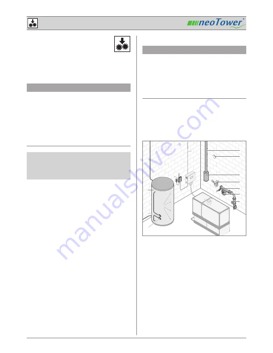
4.2.1 Overview of the installation location
To operate the system, some equipment must be provided
on site. The following illustration shows examples of the
required equipment.
A
B
G
H
I
J
K
L
M
F
C
D
E
A Buffer tank
B Temperature sensor holding fixture
A Buffer water supply line
E Buffer water return line
E Modem
F Supply voltage
G Flue
H Exhaust air opening
I Flue gas silencer
J Condensate drain
K Gas supply
L Gas meter
M Gas flow monitor
The heating system also includes the peak load boiler and
pipework system that connects the system via the buffer
tank.


