‐
33
‐
M
AIN
C
OMMUNICATION
U
NIT
(MCU)
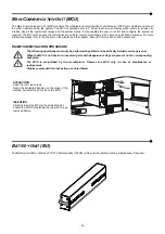
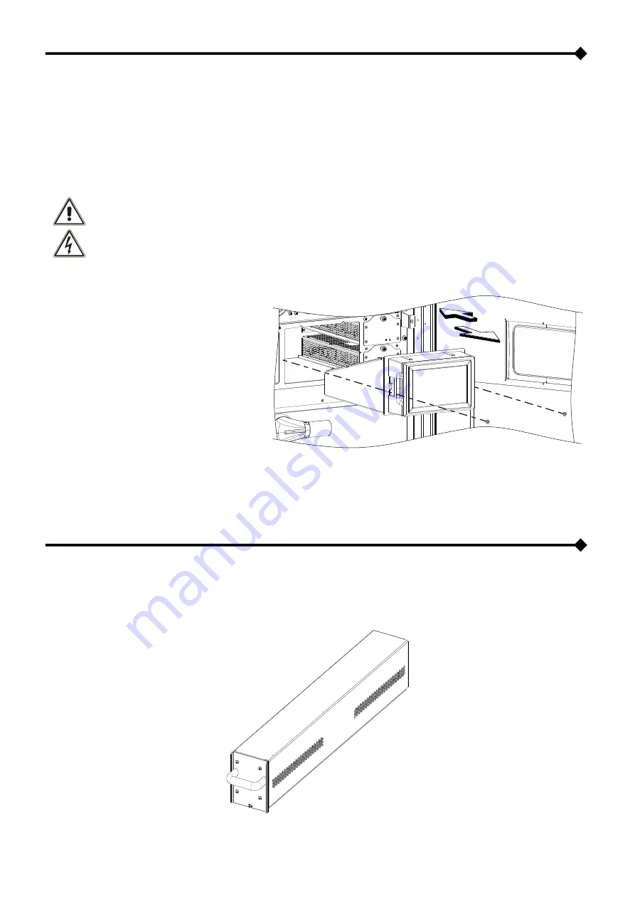
The Main Communication Unit (MCU) monitors the modules and units inserted in the Modular UPS Power Cabinet and also all
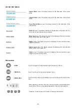
the other Cabinets within the system. The MCU is equipped with a 7” colour touch screen display which shows in an easy an
intuitive way all the operational values and the system status. It also enables the user to control and configure the system as
required. The MCU also houses the communication ports for remote monitoring by the user and authorised personnel. For more
information please refer to the chapter on the display and the chapter “Remote Communication and accessories”.
I
NSERTION
/
EXTRACTION PROCEDURE
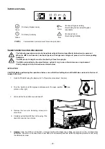
The following operations must only be performed by skilled and specifically trained service personel.
When the MCU is not inserted, uncovered parts with dangerous voltage are present on the corresponding
backplane.
The MCU is preinstalled by the manufacturer. Remove the MCU only in case of maintenance or
replacement.
Strictly comply with the instructions as listed below.
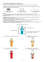
EXTRACTION
Undo the two side screws.
Using the dedicated handles on the sides of the
display, pull carefully and remove the MCU.
INSERTION
Carefully insert the MCU in the dedicated slot.
Fasten the MCU by fastening the two side screws
removed before.
B
ATTERY
U
NIT
(BU)
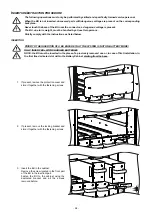
The Battery Unit (BU) contains 10 off 12V battery packs (120Vdc) which can be replaced during maintenance if required.
Summary of Contents for multipower BTC 170
Page 1: ......
Page 2: ......
Page 6: ...6...
Page 8: ...8 GENERAL VIEWS Front view Back view Frame Handle with lock Door Back Panel...
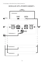
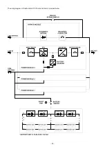
Page 20: ...20 The wiring diagram of the Modular UPS Power Cabinet is provided below...
Page 23: ...23 The wiring diagram of the Modular UPS Combo Cabinet is provided below...
Page 54: ...54 Combo Cabinet...
Page 55: ...55 Battery Cabinet...
Page 82: ......
Page 83: ......
Page 84: ...0MNMPWK25R1ENUA...

