


‐
19
‐
M
ANUAL
B
YPASS
M
ODE
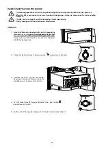
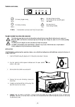
CAUTION: The SWMB disconnection switch installed in the Modular UPS Cabinet is not a maintenance
bypass switch, therefore, there are dangerous voltages within the Cabinet, even if this disconnection switch
is closed.
CAUTION: Contact a service centre should any malfunctions be detected. Maintenance can be carried out
only by skilled staff authorised by the manufacturer.
CAUTION: dangerous voltages can be present inside the device, even if the input, bypass, output and
battery switches are open.
The removal of any enclosure panels from the Modular UPS Cabined by non-skilled personnel is dangerous
and may cause damage to the operator, to the equipment and to the loads connected to it.
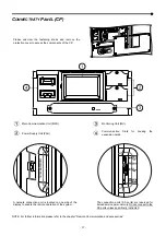
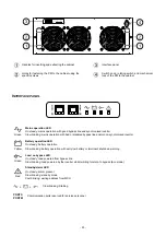
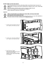
Transferring the Modular UPS system into the MANUAL BYPASS MODE must be performed as follows to ensure that power to
the connected load is not lost.
Caution: if the system is in battery mode, operation of the Manual Bypass may disrupt the power to the connected load.
Close the Manual Bypass SWMB disconnection switch located behind the door, by rotating the handle clock-wise: at this
point the input is directly connected to the output
.
During this mode of operation, any disturbances or blackouts on the power supply line will directly affect the connected
equipment (the Modular UPS Cabinet is no longer active and the load is directly connected to the network).
The display will show that the system has now been transferred to Manual Bypass.
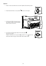
Transferring the Modular UPS system from the MANUAL BYPASS MODE to NORMAL MODE must be performed as follows to
ensure that power to the connected load is not lost. (Perform this only if no anomalies or malfunctions are present):
1.
Ensure that the Bypass Module (see the “Modules and Units” chapter) is present and switched on.
2.
Open the SWMB disconnection switch by rotating the handle anti-clockwise.
3.
The Bypass Module activates and then the entire Modular UPS Cabinet is switched on.
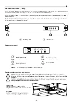
M
ODULAR
UPS
P
OWER
C
ABINET
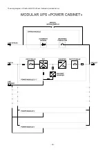
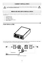
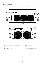
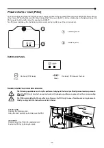
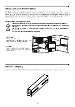
The Modular UPS Power Cabinet PWC 300 is a cabinet that can contain up to 7 (PM25 or PM42) Power Modules and one Bypass
Module (BM) whereas the Modular UPS Power Cabinet PWC 130, can contain up to 5 (PM25) Power Modules and one Bypass
Module (BM).
PMs are UPSs connected in parallel in order to increase reliability in the supply of power to the load and the power available at
the system output (ref. to the "Modules and Units" chapters)
The load that can be applied to a Modular UPS Cabinet can be higher than the load that can be sustained by each unit thanks to
automatic power-sharing. Increased reliability is only achieved on condition that the total system power, with one or more PMs
deactivated, remains higher than the load required. This condition is always achieved by adding at least one redundant PM to the
minimum number of elements required to power the load, so that after the automatic exclusion of a faulty PM, the power supply
can continue in a correct manner.
Each PM is equipped with a smart control unit, connected through a data bus with the other PMs within the system, achieving a
high reliability distributed logic.
Note:
any redundancy of the PMs may be set-up during configuration, but, in the case of a Modular UPS Power Cabinet PWC
300 equipped with all of the 7 PMs, one of them will operate as a redundant module.
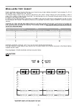
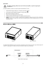
The Bypass Module (BM) operates as the central AUTOMATIC BYPASS for the entire Modular UPS Cabinet (ref. to chapter
“Modules and Units”).
In order to further increase the power of the system, multiple Modular UPS Power Cabinets can be connected in parallel, up to 4.
The maximum configuration will therefore be 28 PMs connected in parallel, of which at least 4 are redundant.
CAUTION: the Modular UPS System has only a single battery supply, therefore all the Modular UPS Cabinets must share
their batteries.
Summary of Contents for multipower BTC 170
Page 1: ......
Page 2: ......
Page 6: ...6...
Page 8: ...8 GENERAL VIEWS Front view Back view Frame Handle with lock Door Back Panel...
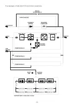
Page 20: ...20 The wiring diagram of the Modular UPS Power Cabinet is provided below...
Page 23: ...23 The wiring diagram of the Modular UPS Combo Cabinet is provided below...
Page 54: ...54 Combo Cabinet...
Page 55: ...55 Battery Cabinet...
Page 82: ......
Page 83: ......
Page 84: ...0MNMPWK25R1ENUA...


