
‐
37
‐
I
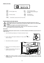
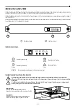
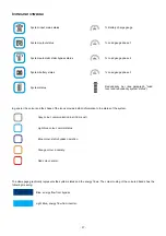
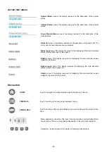
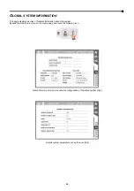
CONS AND SYMBOLS
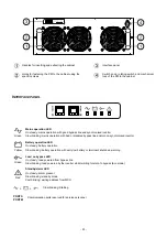
System input mains status
% Battery charge gauge
System output status
% Load gauge phase 1
System automatic static bypass status
% Load gauge phase 2
System battery status
% Load gauge phase 3
System status
Redundancy bar (see paragraph “Load
level and redundancy system status”)
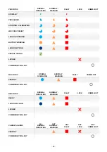
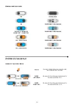
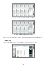
In general, the colour and the shape of the icons provide instant information to the status of the system.
Grey colour: communication lost (Com-Lost).
Light blue colour: normal status.
Blue colour: static bypass operation.
Orange colour: anomaly.
Red colour: alarm.
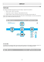
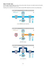
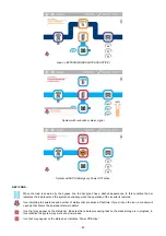
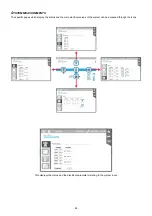
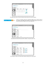
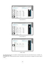
The Homepage graphically represents the system status and the energy flows. The colour coding of the coloured bands has the
following meaning:
Blue, energy flow from bypass.
Light Blue, energy flow from inverter.
Summary of Contents for multipower BTC 170
Page 1: ......
Page 2: ......
Page 6: ...6...
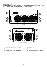
Page 8: ...8 GENERAL VIEWS Front view Back view Frame Handle with lock Door Back Panel...
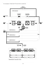
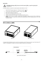
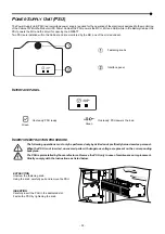
Page 20: ...20 The wiring diagram of the Modular UPS Power Cabinet is provided below...
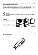
Page 23: ...23 The wiring diagram of the Modular UPS Combo Cabinet is provided below...
Page 54: ...54 Combo Cabinet...
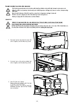
Page 55: ...55 Battery Cabinet...
Page 82: ......
Page 83: ......
Page 84: ...0MNMPWK25R1ENUA...


