background image

6-38

DDP70 Finisher Maintenance Manual

M M

L

0 0

6.7.7. Adjusting the Paper Exit Opening Lower Guide Plate

Applicable jigs and tools:


Screwdriver.

[Disassembling Procedures]

1. Remove the Rear Cover and the Top Cover. 

(Refer to item 6.1.1 on page 6-1)

[Adjustment Procedures]

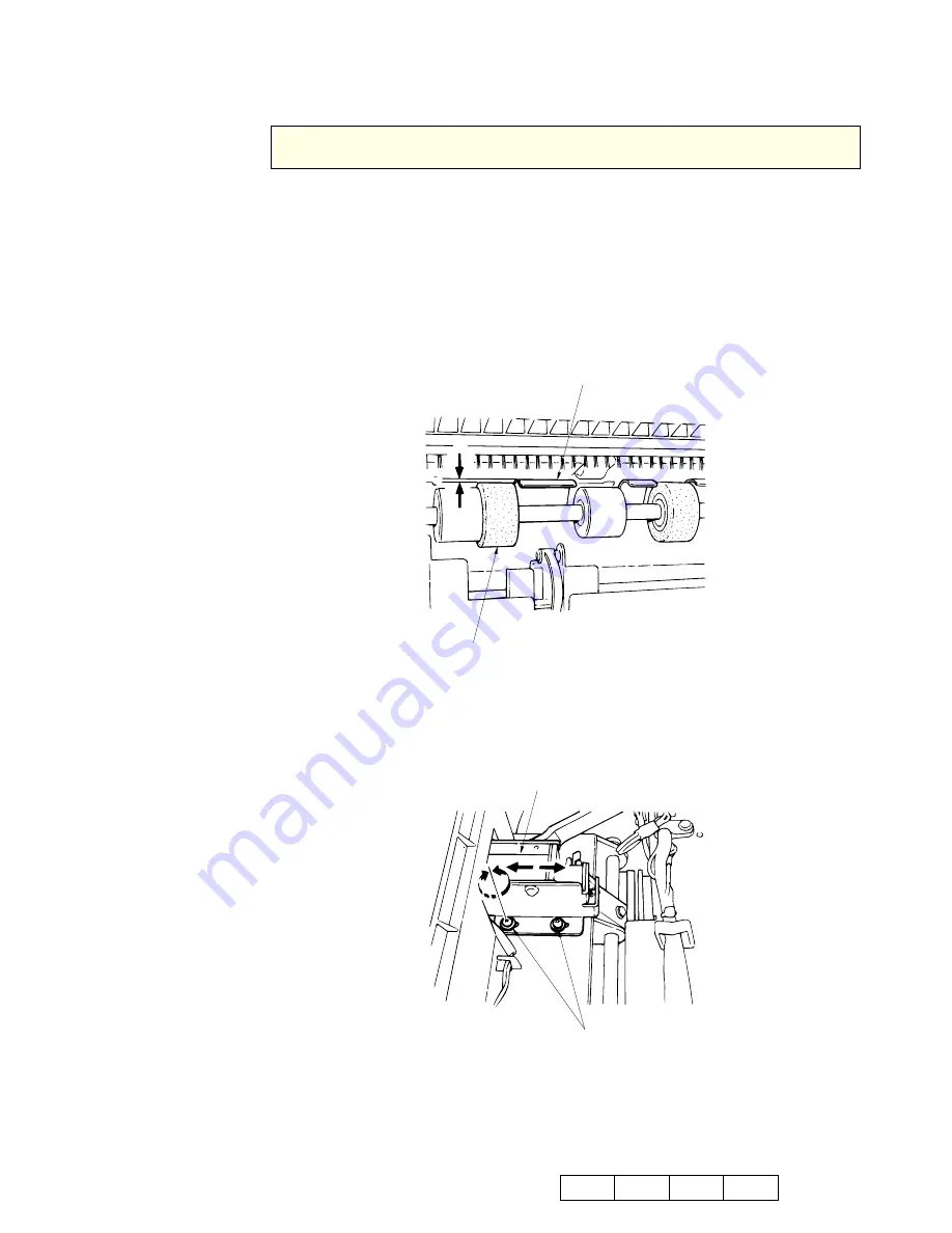
1. When the Paper Exit Opening Solenoid (SD4) is OFF, check whether the value of 

the Lower Guide Plate is greater than that of the Paper Exit Roller.

Figure  6-64. Adjustment of the Paper Exit Opening Lower Guide Plate

2. Loosen the two Solenoid Bracket 

 screws then move and adjust the Solenoid. 

3. Tighten the Solenoid Bracket 

 screws. 

Figure  6-65. Adjustment of the Paper Exit Opening Lower Guide Plate

[Assembling Procedures]

1. Reinstall the Rear Cover and the Top Cover by reversing the procedure above.

CAUTION:
Be sure to turn OFF the MAIN AC POWER prior to performing the maintenance.

LOWER GUIDE PLATE

PAPER EXIT ROLLER

A

A = 1.5 mm  minimum

BRACKET/SOLENOID


SCREWS

Summary of Contents for DDP70

Page 1: ...Standard Finisher Maintenance Manual 2005 Ricoh Printing Systems Ltd May 2005 N901402...

Page 2: ...g Systems Ltd assumes no responsibility for errors or omissions in this document No liability is assumed for any damages resulting from the use of the information it contains NOTICE TO USER In an effo...

Page 3: ...Manual Click on blue to view Table of Contents 1 Outlines 2 Safe Handling of Finisher 3 General Information 4 Preventive Maintenance 5 Troubleshooting 6 Disassembling Assembling Adjustment 7 Theory o...

Page 4: ...i DDP70 Finisher Maintenance Manual Copyright 2005 Ricoh Printing Systems Ltd N901402...

Page 5: ...ii DDP70 Finisher Maintenance Manual...

Page 6: ...i Revisions Page Rev Machine Rev Page No Contents Date 00 First Edition May 2005...

Page 7: ...ii...

Page 8: ...Safety iii Safety Safety in Operation...

Page 9: ...iv DDP70 Finisher Maintenance Manual...

Page 10: ...6 Replacing the Conveyance Roller A and Pulley F 4 11 4 3 7 Replacing the Conveyance Motor M1 4 12 4 3 8 Replacing the Conveyance Motor M7 4 13 4 3 9 Replacing the Grip Solenoid 4 14 4 3 10 Replacing...

Page 11: ...2 Removal of the Neutralizing Brush 6 13 6 5 Removal of the Shift Tray Parts 6 14 6 5 1 Removal of the Shift Tray 6 14 6 5 2 Removal of the Paper Exit Stopper Plate 6 15 6 5 3 Removal of the Up down S...

Page 12: ...3 3 Sub tray Exit Mode 7 5 7 3 4 Staple Mode 7 6 7 4 Conveyance Section 7 8 7 4 1 Construction 7 8 7 4 2 Mechanism 7 8 7 4 2 1 Paper Conveyance 7 8 7 4 2 2 Paper Path Switching 7 9 7 4 2 3 Offset Ope...

Page 13: ...iv DDP70 Finisher Maintenance Manual...

Page 14: ...x18 SEF SEF Short Edge Feed LEF Long Edge Feed Non staple mode only Weight Non staple mode 16 to 110 Index lbs Sub tray exit mode 16 to 42 lbs Staple mode 16 to 34 lbs Option for over 34 to 110 Index...

Page 15: ...ets 80 g m2 5 0 mm and below Stapling position 3 places Stapling capacity 5 000 staples cartridge Power source 24V 5V Supplied from the printer Temperature and 1 Operation Humidity Temperature 10 to 3...

Page 16: ...tlines 1 3 M M L 0 0 1 3 Configurations The basic configuration of this finisher is as follows Finisher Main Frame Cover Paper Conveyance Shift Unit Paper exit Unit Shift Tray Stacker Unit Stapler Uni...

Page 17: ...1 4 DDP70 Finisher Maintenance Manual M M L 0 0...

Page 18: ...otating part is very dangerous as it cannot be seen when rotating During work pay attention to ties sleeves shirts and long hair so that they may not be caught in the finisher Always wear a working ca...

Page 19: ...2 2 DDP70 Finisher Maintenance Manual M M L 0 0...

Page 20: ...ollowing 3 1 Maintenance Precautions 1 Thoroughly read through and understand the instructions to handle the finisher safely as described in Chapter 2 Safe Handling of the Finisher on page 2 1 2 Do no...

Page 21: ...ps Screwdriver No 2 MediumShaft length approx 100mm 2 Jeweler s Screwdriver Set Tip width 2 0 to 2 5 mm 3 Long Nose Chain Plier with side cutter Radio Nipper 4 Push Pull Scale 3 kg 5 Adjustable Open E...

Page 22: ...Block 1 Conveyance Motor M1 M1 4 3 7 Page 4 12 8 1 FS 2 Roller Shift Motor M2 3 1 FS 3 Tray Up down Motor M3 4 3 5 Page 4 10 7 16 FS 4 Alignment Plate Motor M5 9 26 FS 5 Conveyance Motor M7 M7 4 3 8 P...

Page 23: ...SD1 8 15 FS 13 Sub tray Paper Exit Solenoid SD2 8 15 FS 14 Grip Solenoid SD3 4 3 9 Page 4 14 3 39 FS 15 Paper Exit Opening Solenoid SD4 4 3 10 Page 4 15 6 8 FS 16 By pass Solenoid SD5 8 15 FS Table 3...

Page 24: ...e 3 5 Names of Switches Sensors No Name Mark s Maintenance Ref Page Parts Catalog Remarks List Ite m No Block 1 Interlock MS1 1 16 FS 2 Sub tray Exit Sensor PS1 4 15 FS 3 Tray Upper Limit Sensor PS2 1...

Page 25: ...14 10 41 FS 14 R Staple HP Sensor PS15 10 41 FS 15 No F Staple Sensor PS16 10 41 FS 16 F Staple HP Sensor PS17 10 41 FS 17 Roller Shift HP Sensor PS18 3 3 FS 18 Stacker Paper Sensor PS20 9 5 FS 19 Sta...

Page 26: ...3 1 2 3 4 5V 5V RTN 24V 24V RTN F CMD BUS P1 GND F STS BUS P GND CPxxx POWER SUPPLY DSE3 N1 GND A6 B6 A7 B7 A8 B8 DSE2 N1 GND F ST SRR N GND J P745 7 8 9 10 1 2 3 4 5 6 11 12 13 14 15 16 CN10 CN9 J P2...

Page 27: ...N6 CN3 PS17 IN PS16 IN PS25 IN STAPLER F MOTOR 6 7 M10 1 3 M10 DRV F M10 DRV R CN6 2 STAPLER R UNIT Rear side PS14 NO R STAPLE SNS 5 6 7 8 9 1 2 3 11 1 VCC GND PS15 R STAPLE HP SNS PS24 R STAPLE 5 A3...

Page 28: ...2 SD2 DRV 24V B7 B8 1 2 P GND SD3 DRV A9 A8 1 2 SD4 DRV 24V B9 B10 SD 1 SD 2 SD 3 SD 4 SD 5 GATE SOLENOID SUB TRAY PAPER EXIT SOLENOID GRIP SOLENOID PAPER EXIT OPENING SOLENOID BY PASS SOLENOID 1 2 CN...

Page 29: ...5 6 4 STAPLER MOVEMENT PS11 VCC PS11 IN GND B1 B2 B3 STAPLER ROTATION PS21 VCC PS21 IN GND B4 B5 B6 HP SNS A7 A8 M12 M12 DRV P GND STAPLER ROTATION MOTOR STAPLER ROTATION PS22 VCC PS22 IN GND B7 B8 B9...

Page 30: ...ineer This section describes maintenance items and the frequencies performed by customer engineers If any maintenance is noted with plural frequencies an inspection is to be made on an earlier schedul...

Page 31: ...05 2 400 k images 10 4 3 1 2 Paper Exit Roller G8501111 N421840 4 800 k images 15 4 3 2 3 Sponge Roller G8501140 N421870 1 800 k images 2 4 3 3 4 Stapler G8501146 N421876 2 500 k staples 10 4 3 4 5 Tr...

Page 32: ...river Disassembling Procedures 1 Open the Front Cover then open the Guide Plate D Figure 4 1 1 Removal of the Middle Sponge Roller 2 Insert a screwdriver into the slot of the Middle Sponge Roller then...

Page 33: ...0 0 Assembling Procedures 1 Align the grooves of the new Middle Sponge Rollers with the shaft 2 Press the rollers until click sounds so that they can be properly installed M711c epc Figure 4 3 Assembl...

Page 34: ...e the Fixing Ring of the Stacker Unit and then remove the Sponge Roller Figure 4 4 Removal of the Sponge Roller Assembling Procedures 1 Reinstall the Sponge Roller of the Stacker Unit by reversing the...

Page 35: ...1 Move the Shift Tray down Refer to item 4 3 5 on page 4 10 Figure 4 5 1 Removal of the Paper Exit Roller 2 Insert a screwdriver into the slot of the Paper Exit Roller then pry the roller open Figure...

Page 36: ...0 Assembling Procedures 1 Align the grooves of the new Paper Exit Roller with the shaft 2 Press the rollers until click sounds so that they can be properly installed M711c epc Figure 4 7 Assembling of...

Page 37: ...dures 1 Open the Front Cover 2 Pull the release shaft and open the stapler section Figure 4 8 1 Removal of the Stapler 3 Lower the Stapler Unit then disconnect the connector from the Stapler Figure 4...

Page 38: ...4 9 M M L 0 0 4 Remove the screw of the Stapler 5 Lift up the Stapler and remove M711c epc Figure 4 10 3 Removal of the Stapler Assembling Procedures 1 Reinstall the Stapler by reversing the procedur...

Page 39: ...e the Connector and the two screws then remove the Tray Up down Motor M3 Figure 4 11 Removal of the Tray Up down Motor Assembling Procedures 1 Reinstall the Tray Up down Motor by reversing the procedu...

Page 40: ...emoval of the Conveyance Roller A and Pulley F 3 Remove the E Ring and the Shaft Holder from the Conveyance Roller A 4 Remove the Conveyance Roller A Figure 4 13 2 Removal of the Conveyance Roller A a...

Page 41: ...Cover Refer to item 6 1 1 on page 6 1 2 Remove the Connector and the screws 3 Remove the Conveyance Motor M1 Figure 4 14 Removal of the Conveyance Motor M1 Assembling Procedures 1 Reinstall the Convey...

Page 42: ...e Rear Cover Refer to item 6 1 1 on page 6 1 2 Remove the Connector and the screws 3 Remove the Conveyance Motor M7 Figure 4 15 Removal of the Conveyance Motor M7 Assembling Procedures 1 Reinstall the...

Page 43: ...ing Procedures 1 Remove the Rear Cover and the Top Cover Refer to item 6 1 1 on page 6 1 2 Remove the Shift Unit Refer to item 6 2 1 on page 6 4 3 Remove the Grip Solenoid from the Shift Unit Assembli...

Page 44: ...rews and the Spring 3 Remove the Paper Exit Opening Solenoid Figure 4 16 Removal of the Paper Exit Opening Solenoid Assembling Procedures 1 Reinstall the Paper Exit reversing the procedure above 2 Adj...

Page 45: ...cedures 1 Remove the Rear Cover Refer to item 6 1 1 on page 6 1 2 Remove the Connectors on the FS 104H P K 3 Remove the FS 104H P K Figure 4 17 Removal of the FS 104H P K Assembling Procedures 1 Reins...

Page 46: ...he Rear cover and the Top cover Refer to item 6 1 1 on page 6 1 2 Remove the E ring Collar A Belt C L 564 Belt E L 180 Shaft holder G8501088 N421817 Driving pulley B Z 24 and Shaft holder G8501088 N42...

Page 47: ...nd Metal from the Rear side 5 Remove the Driving pulley A Belt D L 309 Driving spacer Pulley F Belt I L 234 Driving spacer Gear A Z 27 E ring and Metal from the Rear side 6 Remove the Driving gear B Z...

Page 48: ...stall the two Metal of the Front side by reversing the procedure above 2 Reinstall the Shaft holder G8501064 N421793 of the Front side by reversing the procedure above 3 Reinstall the Shaft holder G85...

Page 49: ...4 20 DDP70 Finisher Maintenance Manual M M L 0 0...

Page 50: ...NON CAUSES CHECK POINTS CORRECTIONS Maintenance Ref Page 1 This phenomenon occurs 1 The paper is curled Replace Paper 2 The paper is skewed at the Paper Exit Unit 1 Paper Exit Opening does not close c...

Page 51: ...2 DDP70 Finisher Maintenance Manual M M L 0 0 Figure 5 1 Vertical Horizontal sizes of paper Paper feed direction Vertical skew A B B Vertical size of paper Horizontal skew C D D Horizontal size of pap...

Page 52: ...per 1 000 staple operations d The gap between the paper and a staple is beyond 1mm NOTE The Finisher has a possibility that this phenomenon may occur 5 times per 1 000 staple operations PHENOMENON CAU...

Page 53: ...Some paper is extremely skewed in a stapled bundle NOTE The Finisher has a possibility that this phenomenon may occur 1 time per 150 staple operations PHENOMENON CAUSES CHECK POINTS CORRECTIONS Mainte...

Page 54: ...IN Entrance Sensor Paper is detected on the FIN Entrance Sensor 5 11 E065 REMOVE PAPER FINISHER Paper On Paper Path 15 Paper Exit 1 or 2 Sensor Paper is detected on the Paper Exit 1 Sensor or the Pape...

Page 55: ...t Timeout The Print signal of the Finisher is on more than specified time 5 17 E2C1 4C SERVICE CALL E2C1 Stapler Position Error Abnormality was detected in the Staple Movement HP Sensor 5 18 E2C2 4C S...

Page 56: ...ng of connectors Repair the cable CN4 PS3 or reset the connector 3 Sensor fault Replace Tray upper limit sensor PS2 Tray lower limit sensor PS3 3 5 3 5 3 5 3 5 4 PCB fault Replace FS 104H P K 4 3 11 4...

Page 57: ...enance Ref Page 1 This phenomenon occurs due to a lack of staples the number of staples is less than 50 1 Lack of Staples Supply the Staple 2 This phenomenon occurs though the staple plates are in the...

Page 58: ...HP SNS PS25 F STAPLE 5 A4 B2 B1 B8 A7 READY SNS CN110 CN39 CN3 PS17 IN PS16 IN PS25 IN STAPLER F MOTOR 6 7 M10 1 3 M10 DRV F M10 DRV R CN6 2 STAPLER R UNIT Rear side PS14 NO R STAPLE SNS 5 6 7 8 9 1 2...

Page 59: ...is open Close the cover 2 This phenomenon occurs though the Finisher Front Cover does not open 1 The Interlock Switch of the Front Cover is broken Replace Interlock Switch MS1 3 5 3 5 2 The mounting...

Page 60: ...substances 2 The face of the Sensor is contaminated Cleaning Sensor see the table 3 The breaking of cables or the disconnecting of connectors Repair the cable or reset the connector 4 The mounting of...

Page 61: ...PER EXIT 1 SNS PS6 A6 A10 B7 STACKER CONVEYANCE PS5 A4 A9 B5 VCC PS4 IN RTN VCC PS6 IN RTN VCC PS5 IN RTN SUB TRAY PAPER EXIT PS1 1 2 3 A5 A7 B6 VCC PS1 IN RTN ENTRANCE 1 2 3 1 2 3 1 2 3 CN156 SNS SNS...

Page 62: ...CORRECTIONS Maintenance Ref Page 1 Paper jam occurs 1 Paper jam occurs Remove Jammed paper 2 Foreign substance is on the paper path Remove Foreign substance 3 Paper Guide is dislocated Check Paper Gui...

Page 63: ...or codes when the sensors are normal Sensor Name Error Code FIN Entrance Sensor E064 Paper Exit 1 Sensor E065 Paper Exit 2 Sensor E065 Stacker Conveyance Sensor E066 Sub Tray Exit Sensor E068 Replace...

Page 64: ...DRV 24V B11 B12 1 2 SD2 DRV 24V B7 B8 1 2 P GND SD3 DRV A9 A8 1 2 SD4 DRV 24V B9 B10 SD 1 SD 2 SD 3 SD 4 SD 5 GATE SOLENOID SUB TRAY PAPER EXIT SOLENOID GRIP SOLENOID PAPER EXIT OPENING SOLENOID BY P...

Page 65: ...3 PCB fault Replace CPxxx Assembly FS 104H P K Refer to Engine Maintenance manual 4 3 11 4 16 2 This phenomenon is eliminated by pressing the Reset Switch 1 PCB fault Replace CPxxx Assembly FS 104H P...

Page 66: ...E262 1 Finisher program fault Check Finisher program 2 PR program fault Check PR program 3 CE program fault Check CE program 2 This phenomenon occurs E264 E266 E268 E26C 1 Finisher program fault Chec...

Page 67: ...reaking of cables or the disconnecting of connectors Repair the cable CN111 M11 or reset the connector in the correct position 4 PCB fault Replace FS 104H P K 4 3 11 4 16 2 This phenomenon occurs thou...

Page 68: ...1 B2 B3 STAPLE ROTATION PS21 VCC PS21 IN GND B4 B5 B6 HP SNS A7 A8 M12 M12 DRV P GND STAPLER ROTATION MOTOR STAPLE ROTATION PS22 VCC PS22 IN GND B7 B8 B9 HP1 SNS HP2 SNS M11 24V 24V M11 DRVA M11 DRVA...

Page 69: ...s phenomenon occurs because the Stapler does not operate 1 Stapler fault Replace Stapler Unit 4 3 4 4 8 2 The breaking of cables or the disconnecting of connectors Repair the cable or reset the connec...

Page 70: ...epair the cable CN2 M12 or reset the connector in the correct position 4 PCB fault Replace FS 104H P K 4 3 11 4 16 2 This phenomenon occurs though the Stapler rotates 1 The sensor is contaminated Clea...

Page 71: ...onnectors Repair the cable CN103 CN8 or reset the connector in the correct position 4 PCB fault Replace FS 104H P K 4 3 11 4 16 2 This phenomenon occurs though the Shift Tray operates 1 The sensor is...

Page 72: ...the connector in the correct position 4 PCB fault Replace FS 104H P K 4 3 11 4 16 2 This phenomenon occurs though the Alignment Plate operates 1 The sensor is contaminated Cleaning Alignment Plate HP...

Page 73: ...perates 1 The sensor is contaminated Cleaning Roller Shift HP Sensor PS18 and its environs 3 5 3 5 2 The mounting of the sensor is faulty Reset the Roller Shift HP Sensor PS18 in the correct position...

Page 74: ...nnecting of connectors Repair the cable CN1 CN5 M7 or reset the connector in the correct position 4 PCB fault Replace FS 104H P K 4 3 11 4 16 2 This phenomenon occurs though the Paper Exit Belt operat...

Page 75: ...ated Check if the sensor is contaminated etc Cleaning Paper Exit Opening Sensor PS12 and its environs 3 5 3 5 2 The mounting of the sensor is faulty Reset the Paper Exit Opening Sensor PS12 in the cor...

Page 76: ...ures 1 Unscrew the five screws to remove the Rear Cover Figure 6 1 Removal of the Rear Cover 2 Open the Front Cover 3 Unscrew the four screws to remove the Top Cover Figure 6 2 Removal of the Top Cove...

Page 77: ...isassembling Procedures 1 Open the Front Cover 2 Unscrew the four screws to remove the Front Cover Figure 6 3 Removal of the Front Cover Assembling Procedures 1 Reinstall the Front Cover by reversing...

Page 78: ...er Disassembling Procedures 1 Unscrew the three screws to remove the Front Side Cover Figure 6 4 Removal of the Front Side Cover Assembling Procedures 1 Reinstall the Front Side Cover by reversing the...

Page 79: ...1 on page 6 1 2 Disconnect the connectors M2 PS16 and SD4 3 Remove the Wiring from the four Clamp positions Figure 6 5 Removal of the Shift Unit 4 Remove the Ground Wire Fixing Screw 5 Remove the clam...

Page 80: ...ve the Belt and Pulley If necessary loosen the belt by the procedure below 8 Unscrew the screw to remove the Shift Unit Figure 6 7 Removal of the Shift Unit Assembling Procedures 1 Reinstall the Shift...

Page 81: ...es 1 Remove the Rear Cover and the Top Cover Refer to item 6 1 1 on page 6 1 2 Unscrew the four screws to remove the Rear Guide Plate Figure 6 8 Removal of the Sub tray Paper Exit Roller 3 Remove the...

Page 82: ...ng and the Shaft Holder from the Sub tray Paper Exit Roller 5 Remove the Sub tray Paper Exit Roller Figure 6 10 Removal of the Sub tray Paper Exit Roller Assembling Procedures 1 Reinstall the Sub tray...

Page 83: ...age 6 3 3 Remove the Shift Unit Refer to item 6 2 1 on page 6 4 4 Remove the Paper Exit opening Unit Refer to item 6 4 1 on page 6 10 5 Remove the Stacker Unit Refer to item 6 6 1 on page 6 21 6 Unscr...

Page 84: ...two front and two rear E rings and the two front and two rear Shaft Holders then take out the Stacker Entrance Roller Figure 6 13 Removal of the Stacker Entrance Roller Assembling Procedures 1 Reinsta...

Page 85: ...1 2 Remove the Front Side Cover Refer to item 6 1 3 on page 6 3 3 Remove the Shift Unit Refer to item 6 2 1 on page 6 4 4 Remove the E ring and then remove the Collar Gear and the Drive Belt Figure 6...

Page 86: ...gure 6 16 Removal of the Paper Exit Opening Unit 8 Remove the Slide Arm Figure 6 17 Removal of the Paper Exit Opening Unit 9 Open the Front Cover and remove the front side E ring and the Shaft Holder...

Page 87: ...crew the four screws to remove the Paper Exit Opening Cover 12 Take the Paper Exit Opening Unit out to the top Figure 6 20 Removal of the Paper Exit Opening Unit Assembling Procedures 1 Reinstall the...

Page 88: ...Neutralizing Brush 2 Stick the new Neutralizing Brush on so that it lines up with the marked line Figure 6 21 Removal of the Neutralizing Brush Assembling Procedures 1 Reinstall the Neutralizing Brush...

Page 89: ...e Rear Cover Refer to item 6 1 1 on page 6 1 2 Remove the Tray Up down Motor Refer to item 4 3 5 on page 4 10 3 Unscrew the two screws lift up and remove the Shift Tray Figure 6 22 Removal of the Shif...

Page 90: ...item 6 5 1 on page 6 14 3 Remove the Front Side Cover Refer to item 6 1 3 on page 6 3 4 Unscrew the four screws to remove the left and right Up down Cover Figure 6 23 Removal of the Paper Exit Stoppe...

Page 91: ...Unscrew the nine screws lift the Up down Stay and take out the Paper Exit Stopper Plate to the lower side Figure 6 26 Removal of the Paper Exit Stopper Plate Assembling Procedures 1 Reinstall the Pape...

Page 92: ...ge 6 15 5 Unscrew the four screws of the Cable Bracket to remove the Up down Stay Figure 6 27 Removal of the Up down Stay Assembling Procedures 1 Reinstall the Up down Stay by reversing the procedure...

Page 93: ...m 6 5 2 on page 6 15 5 Remove the Up down Stay Refer to item 6 5 3 on page 6 17 6 Unscrew each of the two screws of the front and rear Cable Bracket then remove the Up down Stay Figure 6 29 Removal of...

Page 94: ...wn Cable 9 Wrap the short side of the cable from the Cable Bracket being exchanged around the Up down Pulley twice 10 Line the Cable Bracket position up with another Cable Bracket which was not remove...

Page 95: ...ide and fix the cable end Figure 6 33 Removal of the Up down Cable 13 When the Up down Stay is pressed down the four screws of the Cable Bracket will tighten Figure 6 34 Removal of the Up down Cable A...

Page 96: ...page 6 3 4 Remove the Shift Unit Refer to item 6 2 1 on page 6 4 5 Remove the Paper Exit Opening Unit Refer to item 6 4 1 on page 6 10 6 Take out the E ring and Flange then remove the belt and the two...

Page 97: ...gure 6 37 Removal of the Stacker Unit 10 Disconnect the connector PS9 and then remove the wiring from the Clamp Figure 6 38 Removal of the Stacker Unit 11 Unscrew the screw and then remove PS9 Figure...

Page 98: ...ve CN6 and CN3 on the FIN Control Board and the Staple Connectors F and R Then remove the wiring from the Clamp Figure 6 41 Removal of the Stacker Unit 14 Unscrew the four screws to remove the Stacker...

Page 99: ...above Figure 6 43 Removal of the Stacker Unit CAUTION When the Stacker Paper Exit Arm is in the position as that of the diagram below engage the gear so that the notch of the Belt Detection Gear actua...

Page 100: ...m 6 2 1 on page 6 4 5 Remove the Paper Exit Opening Unit Refer to item 6 4 1 on page 6 10 6 Remove the Stacker Unit Refer to item 6 6 1 on page 6 21 7 Tear off the old Neutralizing Brush Figure 6 44 R...

Page 101: ...on 3 Disconnect the connector CN2 from the Finisher Control Board 4 Open the Clamp in for places and then remove the Harness Figure 6 46 Removal of the Stapler Unit 5 Remove the two Springs 6 Remove t...

Page 102: ...ng Adjustment 6 27 M M L 0 0 7 Re7move the E ring fixed by the Shaft and remove the Stapler Figure 6 48 Removal of the Stapler Unit Assembling Procedures 1 Reinstall the Stapler Unit by reversing the...

Page 103: ...Screwdriver Disassembling Procedures 1 Remove the Rear Cover and the Top Cover Refer to item 6 1 1 on page 6 1 2 Unscrew the four screws to remove the Rear Guide Plate Figure 6 49 Adjustment of the Su...

Page 104: ...solenoid plunger and the bracket stopper is the value stated below Value B 5 0 5 mm Figure 6 50 Adjustment of the Sub tray Gate 3 If the value is outside that of the standard stated loosen the two So...

Page 105: ...he Gate Solenoid SD1 is ON check that the distance between the Shorter Gate and the Guide Plate C is the value stated below Value A 5 0 5 mm 2 When the Gate Solenoid SD1 is ON check that the gap betwe...

Page 106: ...noid Installation screws then move and adjust the Sole noid Figure 6 53 Adjustment of the Paper Route Switching Gate 4 Tighten the Solenoid screws Assembling Procedures 1 Reinstall the Rear Cover and...

Page 107: ...Gate 2 When the By Pass Solenoid SD5 is OFF check that the distance between the By Pass Gate and the Guide Plate D is the value stated below Value 5 2 0 5 mm 3 When the By Pass Solenoid SD5 is ON che...

Page 108: ...en the two installation screws then move and adjust the Solenoid Figure 6 56 Adjustment of the By Pass Gate 5 Tighten the Solenoid screws Assembling Procedures 1 Reinstall the Rear Cover by reversing...

Page 109: ...eck that the Roller Shift HP PS18 Actuator lines up with the Shift Unit Installation Plate Notch Figure 6 57 Adjustment of the Shift Position 3 Loosen the Roller Shift HP PS18 Bracket screw then move...

Page 110: ...closed check that the Paper Exit Casing is touching the Stopper Section reliably Figure 6 59 Adjustment of the Paper Exit Opening 2 Loosen the Paper Exit Opening detection PS PS12 Bracket screw then...

Page 111: ...t Opening Solenoid SD4 is ON check that the gap between the Solenoid Plunger and the Bracket Stopper is the value stated below Value A 6 0 0 5 mm Figure 6 61 Adjustment of the Paper Exit Opening Solen...

Page 112: ...and adjust the Sole noid Figure 6 63 Adjustment of the Paper Exit Opening Solenoid 4 Return the Solenoid to the original position and tighten the Solenoid Bracket screws Assembling Procedures 1 Reinst...

Page 113: ...late is greater than that of the Paper Exit Roller Figure 6 64 Adjustment of the Paper Exit Opening Lower Guide Plate 2 Loosen the two Solenoid Bracket screws then move and adjust the Solenoid 3 Tight...

Page 114: ...er to item 6 5 3 on page 6 17 Adjustment Procedures 1 Loosen the four screws 2 Using the push pull gauge pull the Pulley Shaft of the Belt Tensioner to the level of the value stated below then tighten...

Page 115: ...he Alignment Plate HP Figure 6 67 Adjustment of the Paper Exit Opening Lower Guide Plate 2 Loosen the two screws and adjust the Alignment Plate gap A so that it is within the value stated below Value...

Page 116: ...the value A stated below using a tension gauge or spring balance then tighten the screws Value A 0 5 kg Figure 6 69 Adjustment of the Alignment Drive Timing Belt Tension CAUTION Be sure to turn OFF t...

Page 117: ...o the Stapler Unit so that the rotation hole and the hole of the Installation Plate line up Figure 6 70 Adjustment of the Stapler Rotation Drive Section Installation CAUTION Be sure to turn OFF the MA...

Page 118: ...1 on page 6 1 Adjustment Procedures 1 Loosen each of the two front and rear Stapler screws and move and adjust the Stopper 2 Tighten the Stopper screws Figure 6 71 Adjustment of the Stapler 2 Positio...

Page 119: ...n the two screws then move and adjust the Adjustment Plate 2 Tighten the screws Figure 6 72 Adjustment of the Stapler 2 Position Mechanism Assembling Procedures 1 Reinstall the Stapler R and F by reve...

Page 120: ...te screws then move and adjust the Adjustment Plate 2 Tighten the screws Figure 6 73 Adjustment of the Stapling Position for 1 Position Stapling CAUTION Be sure to turn OFF the MAIN AC POWER prior to...

Page 121: ...el of value A stated below using a push pull gauge or spring balance and then tighten the screws Value A 0 5 kg Figure 6 74 Adjustment of the Tension of the Stapler Move Timing Belt CAUTION Be sure to...

Page 122: ...L 0 0 Chapter 7 Theory of Operation 7 1 Center Cross Section Figure 7 1 View of the Center Cross Section of the Finisher SHIFT TRAY PAPER EXIT SUB TRAY SHIFT UNIT GATE SUB TRAY GATE BY PASS GATE STAC...

Page 123: ...e System Diagram 7 2 1 Paper Conveyance Drive Figure 7 2 View of the Paper Conveyance Drive PRINTER PAPER EXIT ROLLER CONVEYANCE SLIDE SHAFT CONVEYANCE MOTOR M1 CONVEYANCE ROLLER C MIDDLE SPONGE ROLLE...

Page 124: ...eration 7 3 M M L 0 0 7 2 2 Stacker Drive Figure 7 3 View of the Stacker Drive PAPER EXIT ROLLER CONVEYANCE MOTOR M7 STACKER ENTRANCE MOTOR M14 PAPER EXIT ARM SPONGE ROLLER STACKER ENTRANCE PAPER EXIT...

Page 125: ...h a paper shifted 30mm to the rear Off set function a Release the pressure of the pressure roller SD3 b The paper is gripped and moved 30mm to the rear c The pressure roller applies pressure to the pa...

Page 126: ...w of the Non staple Mode 7 3 3 Sub tray Exit Mode A paper exited from the main body is conveyed and exited to the Sub Tray Figure 7 6 View of the Sub tray Exit Mode GATE SUB TRAY GATE CONVEYANCE CONVE...

Page 127: ...hrough Convey ance roller B 4 The alignment plate unit lines up paper in the width wise direction 5 Paper is stapled 6 The first stack is conveyed by the paper exit arm and exited to the shift tray Fi...

Page 128: ...neously sent to the stacker The steps 1 to 3 above are for paper to a maximum of LT size 4 The sponge roller of the stacker section sends the paper to the stopper and the paper is lined up in the leng...

Page 129: ...tacker is performed by the stacker entrance roller and sponge roller These are driven by the stacker entrance motor M14 via the timing belt Paper exiting is performed by the stacker paper exit belt cl...

Page 130: ...solenoid SD5 Figure 7 10 View of the Paper Path Switching 7 4 2 3 Offset Operation Figure 7 11 View of the Offset Operation 1 The Grip Solenoid SD3 turns ON and the pressure of the pressure roller is...

Page 131: ...oller shift motor M2 cam and link mechanism Figure 7 14 View of the Offset Operation 4 Paper is moved 30 mm to the rear and separated and the gripping section returns to the original position Figure 7...

Page 132: ...er exit opening The paper exit belt is rotated by the conveyance motor M7 Figure 7 16 View of the Stacker Unit 7 4 2 5 Paper Exit Opening Unit 1 Stapling mode for paper sized A4R and above The Paper e...

Page 133: ...8 Figure 7 18 View of the Paper Exit Opening Unit 3 Pressure of the paper exit roller The paper exit roller rotation is slower than the conveyance rollers A B and C There fore pressure is released at...

Page 134: ...19 View of the Paper Exit Opening Unit SHIFT TRAY PAPER EXIT OPENING PAPER EXIT OPENING SOLENOID SD4 CONVEYANCE CONVEYANCE CONVEYANCE CONVEYANCE ROLLER ROLLER C ROLLER B ROLLER A PRESSURE ROLLER PAPER...

Page 135: ...n One Place 1 The stapler F and R moves to the stapling position Movement of the stapler F and R is performed by the stapler moving motor M11 2 Paper arranged within the stacker is stapled with either...

Page 136: ...ration The staple operation is driven by the F and R stapler motors M9 and M10 and oper ated by the cam rotation The home position sensors PS15 and PS17 detect that one operation has been per formed W...

Page 137: ...7 16 DDP70 Finisher Maintenance Manual M M L 0 0...

Reviews: