1-18
Container Stacker Installation Instructions
20.
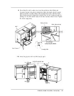
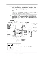
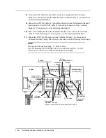
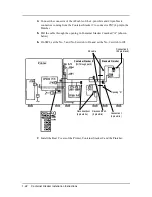
Disconnect the 4 pin white connector of the DC IF cable of the Printer from the
FNS IF cable (Disconnection 1 on the figure below), then connect it to the RB
cable of the 4 pin white connector coming from Container Stacker (Connection 5
on the following illustration) (70/92 ppm only).
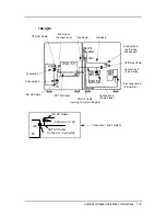
21.
Connect the CS relay cable of accessory box of the printer to the 4 pin white
connector of the FNS IF cable and the RB cable of the 4 pin white translucent
connector of the Container Stacker (Connection 5 on the following illustration.)
(184ppm only)
NOTE
:
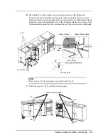
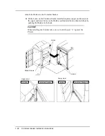
Put the cable through opening “A” of the Printer.
On SW1 mounted on the CPXXX P/K, set switch No. 5 to ON and set switch No. 2
and No. 8 to OFF. (Front Engine of 184 ppm printer)
J23
CST AC Cable
CE AC Cable
Connector : 2 pin white
Connector : 2 pin
PS
Connection 1 and 2 Details
70/92 ppm
CTS AC Cable
M4 Screw
(Connection 3)
Opening A
RB Cable
Connection 5
(4 pin white)
Disconnection 3
(2 pin white)
Connection 4
(20 pin black)
CST FG Cable
CE AC Cable
Connection 2
Connection 1
FNS IF Cable
Disconnection 2
(4 pin white)
Disconnection 1
(4 pin white)
DC IF Cable
Summary of Contents for Container Stacker
Page 5: ...ii Table of Contents ...

