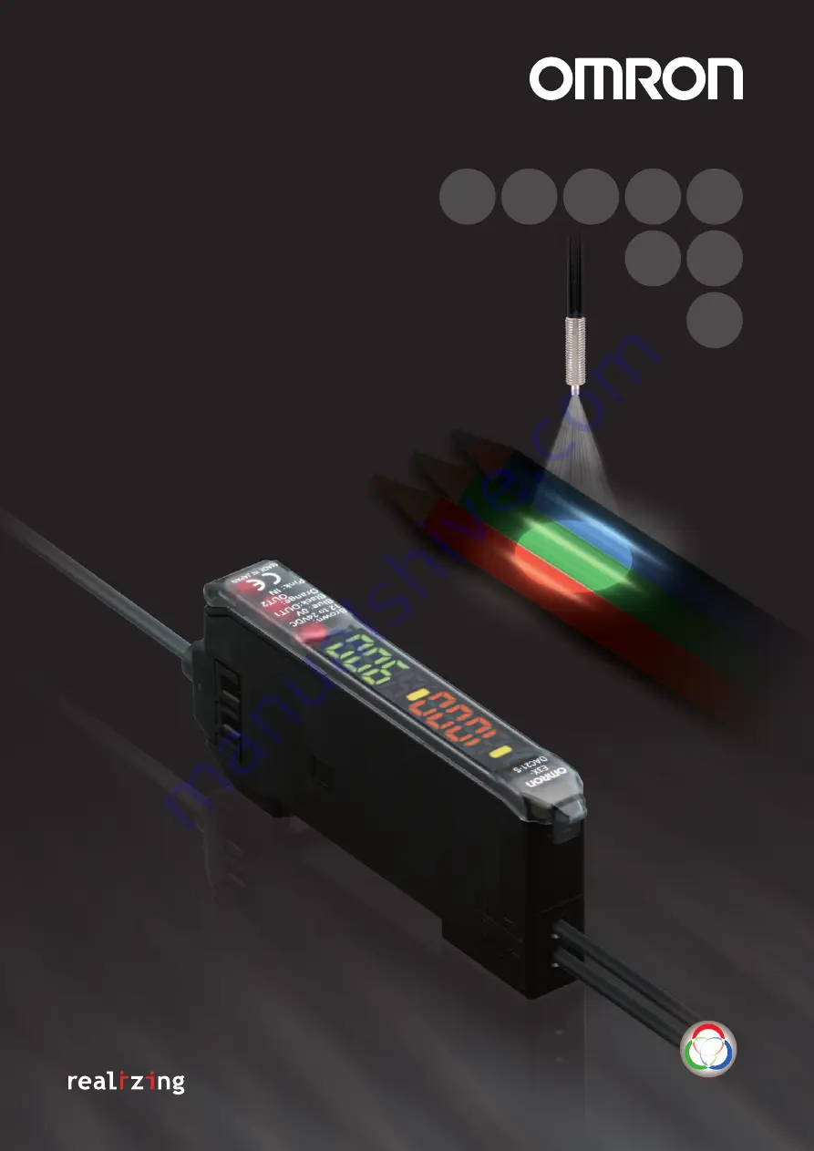
E3X-DAC-S
Color Sensing
Digital Fiber Sensor
Easy and Reliable
The Fiber Sensor
That
Sees
in
Color
C
olor
S
ensing
New Model with Four-color Determination for Even More Complete Color-sensing Fiber Sensors
Page 1: ...3X DAC S Color Sensing Digital Fiber Sensor Easy and Reliable The Fiber Sensor That Sees in Color Color Sensing New Model with Four color Determination for Even More Complete Color sensing Fiber Sensors ...
Page 2: ...n Resists Movement Digital value Distance change 20 10 10 20 100 50 0 50 100 0 90 100 100 100 80 10 10 90 A high power white LED and a multi RGB processing system combine to cover all RGB wavelengths enabling easy and accurate detection of workpieces without having to use a different light source to match each one No Need to Select Not affected Affected White Red Yellow red Yellow Yellow green Gre...
Page 3: ...sdetec tion Color Detection 10 mm Easy and Reliable Ease of Use and Smart Functions In addition to ensuring easy use we have added a number of smart functions such as remote control to simplify setup and twin sensing and output to simultaneously distinguish two registered colors advanced models Ampl i fi e r Un i t A Slim 10 mm wide Amplifier Unit Thinnest in the Industry First in Its Class Use of...
Page 4: ...gh beam Fiber Heads are capable of detecting color differences in semi transparent objects In Black Mode black seam tape and other black marks can be detected regardless of film color or patterns If you teach the conveyor i e the background you can detect workpieces even if they have different colors shapes or gloss Workpieces that absorb a specific wavelength can be detected with a wide range of ...
Page 5: ...setting E3X DAC21 S 2M E3X DAC51 S 2M Advanced models 4 color determination Standard models Determination 4 col ors AND OR output bank switching E3X DAC21B S 2M E3X DAC51B S 2M Item Appearance Functions Model NPN output PNP output Standard models Timer Response speed change E3X DAC6 S E3X DAC8 S Item Appearance Cable length No of conductors Model Master Connector 2 m 3 E3X CN11 Slave Connector 1 E...
Page 6: ...ion allowable range Teaching one point teaching or teaching with without workpiece or manual adjustment Functions Operating mode ON for match ON for same color as registered color or ON for mismatch ON for different color from regis tered color Timer function Timer type OFF delay ON delay or one short Timer time 1 ms to 5 s variable Control outputs Output for each channel AND output and OR output ...
Page 7: ...er Polycarbonate PC Accessories Instruction manual Type Standard models Advanced models 2 color simultaneous determination Advanced models 4 color determination Item Model E3X DAC S 11 41 6 8 E3X DAC S 21 51 E3X DAC B S 21 51 Color 11 standard colors Munsell color notation White N9 5 Red 4R 4 5 12 0 Yellow red 4YR 6 0 11 5 Yellow 5Y 8 5 11 0 Yellow green 3GY 6 5 10 0 Green 3G 6 5 9 0 Blue green 5B...
Page 8: ... 12 9 7 4 Size Sensing direction Model Sensing distance mm Opaque object Translucent object High resolution mode Standard mode High speed mode Super high speedmode High resolution mode Standard mode High speed mode Super high speedmode 1 5 dia Top view E32 T22B 2M 70 55 48 40 15 11 9 6 3 dia E32 T12R 2M 150 110 95 50 30 22 18 16 Side view E32 T14LR 2M 55 44 38 19 12 8 5 7 6 5 Size Sensing directio...
Page 9: ... paper Standard color card 11 colors mutual determination High resolution mode Standard mode High speed mode Super high speedmode High resolution mode Standard mode High speed mode Super high speedmode 6 dia 50 E32 L15 2M 40 to 80 40 to 80 40 to 80 40 to 80 40 to 55 40 to 55 Sensing direction Aperture angle Model Sensing distance mm Opaque object Translucent object High resolution mode Standard mo...
Page 10: ...6 5 3 5 Size Model Sensing distance mm Opaque object Translucent object High resolution mode Standard mode High speed mode Super high speedmode High resolution mode Standard mode High speed mode Super high speedmode 1 5 dia E32 T22B 2M 70 55 48 40 15 11 9 6 M3 E32 T21 2M M4 E32 T11 2M 190 140 120 60 40 28 24 20 Square E32 T25XB 2M 55 42 36 30 11 8 7 4 5 Size Model Sensing distance mm White paper S...
Page 11: ... 150 80 50 36 30 26 E32 T16JR 2M 200 160 130 65 44 30 26 22 30 mm E32 T16WR 2M 360 280 240 120 75 55 46 40 Type Sensing width Model Sensing distance mm White paper Standard color card 11 colors mutual determination High resolution mode Standard mode High speed mode Super high speedmode High resolution mode Standard mode High speed mode Super high speedmode Array 11 mm E32 D36P1 2M 35 26 22 9 7 5 5...
Page 12: ...n not possible Use 2 point teaching to distinguish between white and black White Red Yellow red Yellow Yellow green Green Blue green Blue Blue purple Purple Red purple Black White Red Yellow red Yellow Yellow green Green Blue green Blue Blue purple Purple Red purple Black 0 20 40 60 80 100 120 140 0 X 35 30 25 20 15 10 5 E3X DAC S Number of colors differentiated combinations Sensing distance X mm ...
Page 13: ...ation indicator orange Output transistor Load relay Model Operation mode Timing charts Operation selector Output circuit E3X DAC41 S E3X DAC8 S ON for match LIGHT ON L ON ON for mis match DARK ON D ON E3X DAC51 S E3X DAC51B S ON for match LIGHT ON L ON ON for mis match DARK ON D ON Match Mismatch ON OFF ON OFF Operate Reset Between blue and black leads Operation indicator orange Output transistor ...
Page 14: ...al waste 11 Do not use the Sensor in locations subject to direct sun light 12 Burn injury may occur The Sensor surface temperature rises depending on application conditions such as the ambient temperature and the power supply voltage Use caution when operating or performing maintenance on the Sensor Amplifier Units Standard Models E3X DAC S 11 41 6 8 Advanced Models 2 color simultaneous determinat...
Page 15: ...Adding and Removing Amplifier Units Adding Amplifier Units 1 Mount the Amplifier Units one at a time onto the DIN track 2 Slide the Amplifier Units together line up the clips and press the Amplifier Units together until they click into place Removing Amplifier Units Slide Amplifier Units away from each other and remove from the DIN track one at a time Do not attempt to remove Ampli fier Units from...
Page 16: ...er and used in groups Do not however slide the Amplifier Units or attempt to remove any of the Amplifier Units during operation Others Protective Cover Always keep the protective cover in place when using the Am plifier Unit Fiber Unit Design Precautions Applicable Fiber Units Refer to the sensing distance tables on pages 8 to 11 for the Fiber Units that can be used and the sensing distances Ret r...
Page 17: ... 1 18 7 44 3 A Hole for optical communications Mounting Bracket E39 L143 Order Separately SUS304 stainless steel Two 3 2 dia holes The Mounting Bracket can also be used on this side 16 Two M3 Mounting Holes With Mounting Bracket Attached E3X DAC11 S DAC41 S 4 dia 3 conductor Conductor cross section 0 2 mm2 insulator diameter 1 1 mm E3X DAC21 S DAC51 S DAC21B S DAC51B S 4 dia 5 conductor Conductor ...
Page 18: ... Mode indicator Oblong Operation indicator 16 Two M3 Mounting Holes Amplifier Units with Connectors E3X DAC6 S E3X DAC8 S With Mounting Bracket Attached E3X CN11 3 conductor 4 0 mm dia E3X CN12 1 conductor 2 6 mm dia Master Connectors E3X CN11 14 4 2 6 6 2 9 10 0 8 8 4 6 8 10 7 30 2 4 dia 10 2 4 15 1 6 E3X CN11 4 dia vinyl insulated round cable with 3 conductors Conductor cross section 0 2 mm2 Ins...
Page 19: ... SET Mode Page 21 Refer to 5 Setting Functions in SET Mode Switching setting items SET RUN mode Operation Keys Operation Display Remarks Main Display Sub Display Locking and unlocking keys Locks key operation to prevent incorrect operation Page 22 Refer to 6 Convenient Func tions Initialization and user re set Returns the system to its initial state Page 22 Refer to 6 Convenient Func tions UP DOWN...
Page 20: ...etting after teaching Even if the display method for the Display Switch Function is changed the threshold will appear on the sub display when the key is pressed Advanced Models Set the Channel Selector to the desired channel before making any adjustments or settings This is true for all adjustments and settings OVER Move the workpiece away OK Teaching is possible LO Move the workpiece closer When ...
Page 21: ...ncrements 1000 to 5000 1000 ms increments Timer time timer enabled Used to change timer times The timer can be set from 1 ms to 5 s Teaching level Display switch Output setting Timer function Timer time Used to change the orientation of the display Display orientation Example The threshold level at the default setting is When the setting is the threshold level is Used to change the item output on ...
Page 22: ...MODE key Press the DOWN key right after pressing the MODE key MODE MODE RST USER RST INIT UP DOWN MODE MODE Operation canceled Settings initialized USER NO USER The section enclosed by dotted lines applies to user saved settings YES UP DOWN The incident light level on the main display can be set to 0 This is useful when the reference display is to be reset to zero because the match display and the...
Page 23: ...E3X DAC S Color Sensing Digital Fiber Sensor Easy and Reliable The Fiber Sensor That Sees in Color Color Sensing ...
Page 24: ...ent or addition to the above warranty See http www omron247 com or contact your Omron representative for pub lished information 14 Limitation on Liability Etc OMRON COMPANIES SHALL NOT BE LIABLE FOR SPECIAL INDIRECT INCIDENTAL OR CONSEQUENTIAL DAMAGES LOSS OF PROFITS OR PRODUCTION OR COMMERCIAL LOSS IN ANY WAY CONNECTED WITH THE PRODUCTS WHETHER SUCH CLAIM IS BASED IN CONTRACT WARRANTY NEGLIGENCE ...
Page 25: ...Brasil 55 11 2101 6300 www omron com br OMRON ARGENTINA SALES OFFICE Cono Sur 54 11 4783 5300 OMRON CHILE SALES OFFICE Santiago 56 9 9917 3920 OTHER OMRON LATIN AMERICA SALES 54 11 4783 5300 OMRON INDUSTRIAL AUTOMATION THE AMERICAS HEADQUARTERS Schaumburg IL USA 847 843 7900 800 556 6766 www omron247 com OMRON EUROpE B V Wegalaan 67 69 NL 2132 JD Hoofddorp The Netherlands Tel 31 0 23 568 13 00 Fax...