13
12.
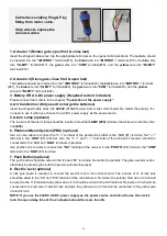
Open the release hole plug on the top of the gate opener, insert the release key, and turn the key 90°
counterclockwise. This restores normal operation.
NOTE: The setting of the PULL/PUSH TO OPEN of the control board should be in accordance with the
installation.
Mounting of the control box
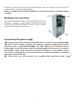
Use 4 deck screws (not provided) to install the control box. Ensure the
control box is installed in a secure surface and at least 100 cm (40
inches) above the ground to protect it from rain, snow, etc. which
probably cause damage to the control box.
Connection of the power supply
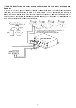
The gate opener must be powered by 2 PCS 12VDC batteries (connected in series, NOT INCLUDED)
If you choose the batteries as the power source, Marine or Automotive Type Battery with capacity
greater than 12 AH is required (NOT INCLUDED). 2 PCS 12VDC batteries can be connected in series to
become 24VDC to power up the gate opener. The following diagram will show you how to connect 2
PCS batteries in series. Please note the wire connection of the batteries is very important. Incorrect
wire connection will damage the control board. The batteries should be waterproof type or you should
place them in water proof housing.
Please ensure other wire connections are completed before connecting the power supply.
Summary of Contents for GTR062
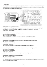
Page 12: ...15 Connection of the control board...
Page 21: ......


